Table of Contents
Advertisement
WARNING: This appliance
is equipped for (Natural and Propane)
gas. Field conversion is not permit-
ted other than between natural or
propane gases.
CAUTION - FOR YOUR SAFETY
WARNING: IF THE INFORMATION IN THIS MANUAL IS NOT FOLLOWED EXACTLY, A FIRE
OR EXPLOSION MAY RESULT CAUSING PROPERTY DAMAGE, PERSONAL INJURY OR
LOSS OF LIFE.
- Do not store or use gasoline or other flammable vapors and Iiquids in vicinity of this or
any other appliance.
WHAT TO DO IF YOU SMELL GAS
• Do not try to light any appliance.
• Do not touch any electrical switch; do not use any phone in your building.
• Immediately call your gas supplier from a neighbor's phone. Follow the gas supplier's instructions.
• If you cannot reach your gas supplier, call the fire department.
- Installation and service must be performed by a qualified installer, service agency or the gas supplier.
This is an unvented gas-fired heater. It uses air (oxygen) from the room in which it is
installed. Provisions for adequate combustion and ventilation air most be provided.
Refer to Air For Combustion and Ventilation section on page 9-11 of this manual.
WARNING: When the appliance is installed directly on carpeting, tile or other combustible material, other than wood
flooring, the appliance shall be installed on a metal or wood panel extending the full width and depth of the appliance.
WARNING: Do not attempt to access or change the setting of the fuel selection means. Access to and adjust-
ment of the fuel selection means must only be a performed by a qualified service person when connecting this
appliance to a specified fuel supply at the time of installation. Change of the selector setting to other than the fuel
type specified at the time of installation could damage this appliance and render it inoperable. The installer shall
replace the access cover before completing the installation and operating this appliance.
WARNING: Any safety screen or guard removed for servicing an appliance must be replaced prior to operat-
ing the heater (see Clause 4.1.6).
This appliance may be installed in an aftermarket, permanently located manufactured (mobile) home, where
not prohibited by local codes. This appliance is only for use with propane or
natural gas. This appliance is equipped with a simple means to switch between propane and natural gas.
Field conversion by any other means including the use of a kit is not permitted.
Questions, problems, missing parts? Before returning to your retailer, call our Technical
INSTALLER: Leave this manual with the appliance.
CONSUMER: Retain this manual for future reference.
Service Department at 1-814-643-1775.
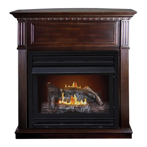
DUAL FUEL FIREPLACE
®
1
VENT-FREE GAS
MODEL #GFD 2043 / 2671 /
3281R / 3291R
Patent Pending
Dual Fuel System
NG
LP
C
C
Dual Fuel
ANS Z21.11.2-2013
80-10-431 - 2018-03-16
US
US
Advertisement
Table of Contents

Subscribe to Our Youtube Channel
Related Manuals for Comfort Glow GFD 2043


Summary of Contents for Comfort Glow GFD 2043
- Page 1 VENT-FREE GAS DUAL FUEL FIREPLACE ® MODEL #GFD 2043 / 2671 / 3281R / 3291R WARNING: This appliance Patent Pending is equipped for (Natural and Propane) Dual Fuel System gas. Field conversion is not permit- ted other than between natural or propane gases.
-
Page 3: Table Of Contents
TABLE OF CONTENTS Specifications ........................... 2 Important Safety Information ......................3 Product Identification ........................5 Product Features ..........................6 Unpacking............................6 Hood Assembly..........................7 Preparing for Installation........................8 Installation ............................11 Operation ............................24 Remote Control Operation.......................26 Care and Maintenance ........................33 Troubleshooting .......................... -
Page 4: Important Safety Information
IMPORTANT SAFETY INFORMATION IMPORTANT: Read this owner’s manual carefully and completely before trying to assemble, operate, or service this heater. Improper use of this heater can cause serious injury or death from burns, fire, explosion, electrical shock, and carbon monoxide poisoning. Only a qualified installer, service agent, or local gas supplier may install and service this product. - Page 5 SAFETY INFORMATION 1. This appliance is only for use with the type of gas indicated on the rating plate. This appliance is not convertible for use with other gases. 2. Do not place propane/LP supply tank(s) inside any structure. Locate propane/LP supply tank(s) outdoors. 3.
-
Page 6: Product Identification
PRODUCT IDENTIFICATION GFD 2043 / 2671 GFD 3281R / 3291R Fireplace Fireplace Cabinet Cabinet Hood Hood Screen Screen Remote Transmitter Ignitor Button Ignitor Button Control Knob EI Receiver Control Knob Fig. 1 - Vent-Free Dual Fuel Fireplace Mantel Cabinet NOTE: The fireplace is installed into the mantel through the front opening of the mantel cabinet. -
Page 7: Product Features
PRODUCT FEATURES SAFETY PILOT This heater has a pilot with an Oxygen Depletion Sensing (ODS) safety shutoff system. The ODS/pilot shuts off the heater if there is not enough fresh air and cuts off main burner gas in the event of flame out. ELECTRIC PUSH BUTTON IGNITION SYSTEM This heater is equipped with an electronic push button control system. -
Page 8: Hood Assembly
HOOD ASSEMBLY (IF REQUIRED) WARNING: Always have screen in place before operating fireplace. This prevents excessive temperatures on fireplace surfaces. WARNING: Failure to position the parts in accordance with these diagrams or failure to use only parts specifically approved with this fireplace may result in property damage or personal injury. -
Page 9: Preparing For Installation
PREPARING FOR INSTALLATION AIR FOR COMBUSTION AND VENTILATION WARNING: This heater shall not be installed in a room or space unless the required volume of indoor combustion air is provided by the method described in the Nation Fuel Gas Code, ANSI Z223.1/NFPA 54, the International Fuel Gas Code, or applicable local codes. - Page 10 PREPARING FOR INSTALLATION DETERMINING FRESH-AIR FLOW FOR HEATER LOCATION Determining if You Have a Confined or Unconfined Space Use this worksheet to determine if you have a confined or unconfined space. Space: Includes the room in which you will install heater plus any adjoining rooms with doorless passageways or ventilation grills between the rooms.
- Page 11 PREPARING FOR INSTALLATION Ventilation Air From Inside Building This fresh air would come from adjoining unconfined space. When ventilating to an adjoining unconfined space, you must provide two permanent openings: one within 12 in. of the wall connecting the two spaces (see options 1 and 2, Fig.
-
Page 12: Installation
INSTALLATION NOTICE: This heater is intended for use as supplemental heat. Use this heater along with your primary heating system. Do not install this heater as your primary heat source. If you have a central heating system, you may run system’s circulating blower while using heater. This will help circulate the heat throughout the house. - Page 13 INSTALLATION FIREPLACE CLEARANCES CAUTION: If you install the fireplace in a home garage • fireplace pilot and burner must be at least 18" above floor. • locate fireplace where moving vehicle will not hit it. For convenience and efficiency, install fireplace •...
- Page 14 INSTALLATION WARNING: This optional blower is equipped with a three-prong (grounding) plug for your protection against shock hazard and must be plugged directly into a properly grounded three-prong receptacle. Firebox must be disconnected from gas supply and removed from mantel before installing fan accessory.
- Page 15 INSTALLATION Important: Insert the wires marked with AUTO, OFF and MAN into line slot on the right corner. Keep wires close to the bottom and guide to the front using the bottom access. Insert two wires’ female plugs marked with T1 and T2 (black and yellow) into two male ports on Temperature Sensor.
- Page 16 INSTALLATION Insert the blower link (male plug) into the power link (female port). Important: Bind wires with cable tie (G), and attach cable tie (G) into the fixed hole from the in side of the Outer Casing. Do the same with the wires through the bottom access.
- Page 17 INSTALLATION Push Rocker Switch (E) into Control Panel and secure. Secure the Green Ground wire to the Grounding screw hole from Screw the inside with the screw. Green Ground Wire Check that all wires are secure and reattach Blower Access Panel to Outer Casing.
- Page 18 INSTALLATION Electrical Wiring Diagram WHITE ~120V 60Hz GREEN BLACK BLUE AUTO OFF MAN 1. Power Cord 2. Bushing Strain Relief 3. Blower 4. Temperature Sensor 5. Rocker Switch NOTE: If any of the original wire as supplied with the appliance must be replaced, it must be replaced with a wire of at least an equal temperature rating.
- Page 19 INSTALLATION GAS SELECTION INSTRUCTIONS WARNING: This appliance can be used with propane or natural gas. It is shipped from the factory adjusted for use with propane. CAUTION: The knob to the gas selection means shall not be accessed or adjusted while the ap- pliance is in operation.
- Page 20 INSTALLATION CONNECTING TO GAS SUPPLY WARNING: A qualified service technician must connect heater to gas supply. Follow all local codes. CAUTION: Never connect heater directly to the gas supply. This heater requires an external regulator (not supplied). The external regulator between the gas supply and heater must be in- stalled.
- Page 21 INSTALLATION CAUTION: Use pipe joint sealant that is resistant to gas (PROPANE or NG). We recommend that you install a sediment trap in a supply line as shown in Fig. 10. Locate sediment trap where it is within reach for cleaning and not likely to freeze. Install in the piping system between fuel supply and heater.
- Page 22 ASSEMBLING LOGS GFD 2043 / 2671 WARNING: Failure to position the parts in accordance with these diagrams or failure to use only parts specifically approved with this heater may result in property damage or personal injury. CAUTION: After installation and peridically thereafter, check to ensure that no yellow flame comes in contact with any log.
- Page 23 ASSEMBLING LOGS GFD 3281R / 3291R WARNING: Failure to position the parts in accordance with these diagrams or failure to use only parts specifically approved with this heater may result in property damage or personal injury. CAUTION: After installation and peridically thereafter, check to ensure that no yellow flame comes in contact with any log.
- Page 24 INSTALLATION CHECKING GAS CONNECTIONS WARNING: Test all gas piping and connections for leaks after installing or servicing. Correct all leaks immediately. WARNING: Never use an open flame to check for a leak. Apply a mixture of liquid soap and water to all joints.
-
Page 25: Operation
LIGHTING INSTRUCTIONS Models GFD 2043 / 2671 1. STOP! Read the safety information as noted above. 2. Open the lower access panel located below the fireplace screen. - Page 26 “MODE” and “SET” functions. Fig.19 - Remote TO TURN OFF GAS TO APPLIANCE Models GFD 2043 / 2671 1. Open the lower access panel located under the fireplace screen. 2. Turn control knob clockwise to the “OFF”...
-
Page 27: Remote Control Operation
REMOTE CONTROL OPERATION MULIT-FUNCTION WIRELESS REMOTE CONTROL SYSTEM FOR OPERATING A LATCHING SOLENOID VALVE, MANUALLY OR WITH A THERMOSTAT FUCTION IF YOU CANNOT READ OR UNDERSTAND THESE INSTALLATION INSTRUCTIONS DO NOT ATTEMPT TO INSTALL OR OPERATE INTRODUCTION This remote control system was developed to provide a safe, reliable, and user-friendly remote control system for gas heating appliances. - Page 28 REMOTE CONTROL OPERATION LCD - Liquid Crystal Display DISPLAY Indicates CURRENT room temperature . F OR Indicates degrees Fahrenheit or Celsius. FLAME Indicates burner/valve in operation. ROOM Indicates remote is in THERMO operation. TEMP Appears during manual operation. ROOM TEMP Appears during time the of setting the desired temperature in the thermo operation.
- Page 29 REMOTE CONTROL OPERATION MULIT-FUNCTION WIRELESS REMOTE CONTROL SYSTEM FOR OPERATING A LATCHING SOLENOID VALVE, MANUALLY OR WITH A THERMOSTAT FUCTION IF YOU CANNOT READ OR UNDERSTAND THESE INSTALLATION INSTRUCTIONS DO NOT ATTEMPT TO INSTALL OR OPERATE INTRODUCTION This remote control system was developed to provide a safe, reliable, and user-friendly remote control system for gas heating appliances.
- Page 30 REMOTE CONTROL OPERATION MULIT-FUNCTION WIRELESS REMOTE CONTROL SYSTEM FOR OPERATING A LATCHING SOLENOID VALVE, MANUALLY OR WITH A THERMOSTAT FUCTION IF YOU CANNOT READ OR UNDERSTAND THESE INSTALLATION INSTRUCTIONS DO NOT ATTEMPT TO INSTALL OR OPERATE INTRODUCTION This remote control system was developed to provide a safe, reliable, and user-friendly remote control system for gas heating appliances.
- Page 31 REMOTE CONTROL OPERATION MULIT-FUNCTION WIRELESS REMOTE CONTROL SYSTEM FOR OPERATING A LATCHING SOLENOID VALVE, MANUALLY OR WITH A THERMOSTAT FUCTION IF YOU CANNOT READ OR UNDERSTAND THESE INSTALLATION INSTRUCTIONS DO NOT ATTEMPT TO INSTALL OR OPERATE INTRODUCTION This remote control system was developed to provide a safe, reliable, and user-friendly remote control system for gas heating appliances.
- Page 32 REMOTE CONTROL OPERATION MULIT-FUNCTION WIRELESS REMOTE CONTROL SYSTEM FOR OPERATING A LATCHING SOLENOID VALVE, MANUALLY OR WITH A THERMOSTAT FUCTION IF YOU CANNOT READ OR UNDERSTAND THESE INSTALLATION INSTRUCTIONS DO NOT ATTEMPT TO INSTALL OR OPERATE INTRODUCTION This remote control system was developed to provide a safe, reliable, and user-friendly remote control system for gas heating appliances.
- Page 33 OPERATION INSPECTING BURNERS Check pilot flame pattern and burner flame patterns often. PILOT FLAME PATTERN Figure 20 shows a correct pilot flame pattern. Figure 21 shows an incorrect pilot flame pattern. The incorrect pilot flame is not touching the thermocouple. This will cause the thermocouple to cool. When the thermocouple cools, the fireplace will shut down.
-
Page 34: Care And Maintenance
CARE AND MAINTENANCE BURNER FLAME PATTERN Figure 22 shows a correct burner flame pattern. Figure 23 shows an incorrect burner flame pattern. The incorrect burner flame pattern shows sporadic, irregular flame tipping. The flame should not be dark or have an orange/reddish tinge. Note: When using the fireplace the first time, the flame will be orange for approximately one hour until the log cures. - Page 35 CARE AND MAINTENANCE 1. Shut off unit including pilot. Allow unit to cool for at least 30 minutes. 2. Inspect burner, pilot and primary air inlet holes on orifice holder for dust and dirt (See Fig. 24). 3. Blow air through the ports/slots and holes in the burner. 4.
- Page 36 TROUBLESHOOTING WARNING: If you smell gas: • Shut off gas supply. • Do not try to light any appliance. • Do not touch any electrical switch; do not use any phone in your building. • Immediately call your gas supplier from a neighbor’s phone. Follow the gas supplier’s instructions. •...
-
Page 37: Troubleshooting
TROUBLESHOOTING PROBLEM POSSIBLE CAUSE CORRECTIVE ACTION 1. Control knob is not fully ODS/pilot lights 1. Press in control knob fully. but flame goes out pressed in. 2. Control knob is not pressed when control knob is 2. After ODS/pilot lights, keep control in long enough. - Page 38 TROUBLESHOOTING PROBLEM POSSIBLE CAUSE CORRECTIVE ACTION 1. Turn heater off when using furniture White powder resi- 1. When heated, the vapors due forming within from furniture polish, wax, polish, wax, carpet cleaner or similar burner box or on carpet cleaners, etc., turn products.
-
Page 39: Replacement Parts
REPLACEMENT PARTS For replacement parts, call our Technical service department at 1-814-643-1775, 8:30 a.m. – 4:30 p.m., CST, Monday – Friday. FIREBOX MODELS GFD 2043 / 2671 / 3281R / 3291R PART NUMBER ITEM DESCRIPTION GFD3281R GFD2043 GFD2671 GFD3291R Top Grille... - Page 40 REPLACEMENT PARTS LIST For replacement parts, call our Technical service department at 1-814-643-1775, 8:30 a.m. – 4:30 p.m., CST, Monday – Friday. GFD 2043 / 2671 GFD 3281R / 3291R...
-
Page 41: Accessories
REPLACEMENT PARTS LIST PART NUMBER ITEM DESCRIPTION GFD2043 GFD2671 GFD 3281R / 3291R Log Set (Complete) 700-S1018 700-M1018 700-L1018 Log 1 700-S1018-01 700-M1018-01 700-L1018-01 Log 2 700-S1018-02 700-M1018-02 700-M1018-02 Log 3 700-S1018-03 700-M1018-03 700-M1018-03 Log 4 700-S1018-04 700-M1018-04 700-M1018-04 Log 5 700-S1018-05 700-M1018-05 700-M1018-05... -
Page 43: Warranty
® G OMFORT PPLIANCE ARRANTY LIMITED WARRANTY: A limited warranty is extended to the original purchaser of this heater and warrants against malfunction due to manufacturing defects for a period of (1) one year from the date of retail purchase. Please read and follow all details noted below. - Page 44 ® G OMFORT PPLIANCE ARRANTY LIMITED WARRANTY: A limited warranty is extended to the original purchaser of this heater and warrants against malfunction due to manufacturing defects for a period of (1) one year from the date of retail purchase. Please read and follow all details noted below.
Need help?
Do you have a question about the GFD 2043 and is the answer not in the manual?
Questions and answers