Table of Contents
Advertisement
Quick Links
Advertisement
Table of Contents

Related Manuals for Chauvin Arnoux F407


Summary of Contents for Chauvin Arnoux F407
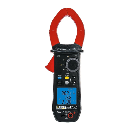
- Page 1 GB - User’s manual F407 Clamp multimeter...
-
Page 2: Table Of Contents
CONTENTS PRESENTATION ......................8 THE SWITCH ........................9 THE KEYS OF THE KEYPAD ..................10 THE DISPLAY UNIT ....................... 11 1.3.1 The symbols of the display unit ..............11 1.3.2 Measurement capacity exceeded (O.L) ............13 THE TERMINALS ......................13 THE KEYS ......................... - Page 3 STARTING CURRENT OR OVERCURRENT (TRUE INRUSH) MEASUREMENT ............................. 29 3.10 POWER MEASUREMENTS W, VA, , PF AND DPF ........... 31 3.10.1 Measurement of single-phase power ............31 3.10.2 Balanced three-phase power measurement ..........32 3.10.3 Four quadrant diagram ................33 3.11 ENERGY METERING MEASUREMENT ..............
- Page 4 ENVIRONMENTAL CONDITIONS ................67 CHARACTERISTICS OF CONSTRUCTION .............. 68 POWER SUPPLY ......................69 COMPLIANCE WITH INTERNATIONAL STANDARDS ........69 VARIATIONS IN THE DOMAIN OF USE ..............70 MAINTENANCE ....................... 71 CLEANING ........................71 REPLACEMENT OF THE BATTERIES ............... 71 WARRANTY ......................72 DELIVERY CONDITION ..................
- Page 5 You have just acquired an F407 clamp multimeter and we thank you. For best results from your device : • read this user manual attentively, • observe the precautions for its use. Meanings of the symbols used on the device Danger.
- Page 6 PRECAUTIONS FOR USE This device complies with safety standards IEC-61010-1 and 61010-2-032 for voltages of 1000V in category IV at an altitude OF less than 2000m, indoors, with a degree of pollution not exceeding 2. These safety instructions are intended to ensure the safety of persons and proper operation of the device.
- Page 7 As a safety measure, and to avoid repeated overloads on the inputs of the device, we recommend performing configuration operations only when the device is disconnected from all dangerous voltages. MEASUREMENT CATEGORIES Definitions of the measurement categories : CAT II: Circuits directly connected to the low-voltage installation. Example: power supply to household electrical appliances and portable tools.
-
Page 8: Presentation
1 PRESENTATION The F407 is a professional electrical measuring instrument that combines the following functions: Current measurement; Measurement of inrush current / overcurrent (True-Inrush); Voltage measurement; Frequency measurement; Measurement of harmonic distortion, total (THD) and order by order;... -
Page 9: The Switch
THE SWITCH The switch has five positions. To access the , functions, set the switch to the desired function. Each setting is confirmed by an audible signal. The functions are described in the table below. Figure 2 : the switch Item Function See §... -
Page 10: The Keys Of The Keypad
THE KEYS OF THE KEYPAD Here are the six keys of the keypad : Figure 3 : the keys of the keypad Item Function See § Storage of values, disabling of display Zero correction A 3.8.2 AC+DC/ AC+DC Selection of the type of measurement (AC, DC) Selection of single-phase or three-phase measurement Activation or de-activation of the backlighting of the display unit... -
Page 11: The Display Unit
THE DISPLAY UNIT Here is the display unit of the clamp multimeter: Figure 4 : the display unit Item Function See § Display of the modes selected (keys) Display of the measurement value and unit 3.13 Display of the MAX/MIN modes 3.10 Type of measurement (AC or DC) Spent battery indication... - Page 12 Maximum RMS value Minimum RMS value Mean RMS value PEAK+ Maximum peak value PEAK- Minimum peak value Balanced total three-phase power measurement Volt Hertz Active power Ampere Percentage Ω Milli- prefix Kilo- prefix Reactive power Apparent power Power factor Displacelent power factor (cos φ) Crest factor RIPPLE Ripple (in DC)
-
Page 13: Measurement Capacity Exceeded (O.l)
Recording in memory BlueTooth wireless communication Continuity test Permanent display (automatic switching off de-activated) Spent battery indicator 1.3.2 Measurement capacity exceeded (O.L) The O.L (Over Load) symbol is displayed when the display capacity is exceeded. THE TERMINALS The terminals are used as follows: Figure 5 : the terminals Item Function... -
Page 14: The Keys
2 THE KEYS The keys of the keypad respond differently to short, long, and sustained presses. In this section, the icon represents the possible positions of the switch for which the key concerned has some action. This key is used to: store and look up the last values acquired specific to each function (V, A, Ω, ... -
Page 15: Key (Second Function)
KEY (SECOND FUNCTION) This key is used to select the type of measurement (AC, DC, AC+DC) and the second functions marked in yellow next to the relevant positions of the switch. It can also be used in the configuration mode, to modify the default values (see §3.4) Remark: the key is invalid in the MAX/MIN/PEAK and HOLD modes. -
Page 16: Key
Successive … serve presses on short to scroll through the various pages of measurement results, depending on the function and possibly the active mode (MAX/MIN/PEAK or THD/Harmonics) long (> 2 sec) to activate/de-activate the back-lighting of the display unit. Remark: the back-lighting is switched off automatically at the end of 2 minutes. -
Page 17: Key
2.5.1 In the normal mode This key activates detection of the MAX, MIN, PEAK+, PEAK- or AVG values of the measurements made. Max and Min are the extreme mean values in DC and the extreme RMS values in AC. Peak+ is the maximum instantaneous peak and Peak- is the minimum instantaneous peak. -
Page 18: Access To The True-Inrush Mode ( Set To )
2.5.2 Access to the True-INRUSH mode ( set to This key allows measurement of the True-Inrush current (starting current, or overcurrent in steady-state operation) for AC or DC current only (not operational in AC+DC). Successive …serves presses on long (>2 sec) to enter the True-INRUSH mode -"Inrh"... -
Page 19: Key
This key is used to display measurements of the frequency of a signal, of power, of the levels and orders of harmonics. Remark : this key is not working in DC mode. 2.6.1 The Hz function in the normal mode Successive …serves presses on... -
Page 20: In The Display Of Orders Of Harmonics Mode
2.6.2 In the display of orders of harmonics mode Successive …serve presses on short to display the frequency of the order of harmonic previously selected using the keys, instead of order hxx. A 2nd short press restores display of order (hxx) or hdC 2.6.3 In Hz mode + activation of the HOLD mode... -
Page 21: Use
3 USE COMMISSIONING Insert the batteries supplied with the device as follows: Using a screwdriver, unscrew the screw of the battery compartment cover (item 1) on the back of the housing and open it. Place the 4 batteries in the compartment (item 2), taking care to get the polarities right. -
Page 22: Switching The Clamp Multimeter
SWITCHING THE CLAMP MULTIMETER The clamp multimeter can be switched off either manually, by setting the switch to OFF, or automatically, after ten minutes with no action on the switch and/or the keys. Thirty (30) seconds before the device is switched off, an audible signal sounds intermittently. -
Page 23: Programming The Rate Of Recording In Memory
To exit from the programming mode, turn the switch to another setting. The chosen threshold is stored (emission of a double beep). Note: The starting current measurement triggering threshold is fixed at 1% of the least sensitive range. This threshold is not adjustable 3.4.3 Programming the rate of recording in memory In the OFF position, hold the... -
Page 24: Voltage Measurement (V)
VOLTAGE MEASUREMENT (V) To measure a voltage, proceed as follows : Set the switch to Connect the black lead to the COM terminal and the red lead to "+". Place the test probes or the crocodile clips on the terminals of the circuit to be measured. -
Page 25: Continuity Test
- in AC and AC+DC Display Quantity Total RMS voltage V RMS or TRMS Crest factor (CF) DC voltage component, V DC CONTINUITY TEST Warning : Before performing the test, make sure that the circuit is off and any capacitors have been discharged. Set the switch to ;... -
Page 26: Resistance Measurement Ω
RESISTANCE MEASUREMENT Ω Warning : Before making a resistance measurement, make sure that the circuit is cold and any capacitors have been discharged. key. The Ω symbol is Set the switch to and press the displayed; Connect the black lead to the COM terminal and the red lead to « + »; Place the test probes or the crocodile clips on the terminals of the circuit or component to be measured ;... -
Page 27: Dc Or Ac+Dc Measurement
The measured values are displayed on the screen. Display Quantity RMS current A RMS Crest factor (CF) DC current component A DC 3.8.2 DC or AC+DC measurement To measure the DC or AC+DC current, if the display unit does not indicate "0", first correct the DC zero as follows: Step 1 : to correct the DC zero Important : The clamp must not be closed on the conductor during the DC zero... - Page 28 Remark : the correction is effected only if the value displayed is < ± 10 A, otherwise the value displayed blinks and is not stored. The clamp must be recalibrated (see § 5.3) Step 2 : to make a measurement The switch is set to .
-
Page 29: Starting Current Or Overcurrent (True Inrush) Measurement
- in AC and AC+DC : Display Quantity Total RMS current in A RMS or TRMS Crest factor (CF) DC current component A DC STARTING CURRENT OR OVERCURRENT (TRUE INRUSH) MEASUREMENT To measure a starting current or overcurrent, proceed as follows: Set the switch to then encircle only the conductor concerned with the clamp. - Page 30 Display Quantity “Inrh” True Inrush value in A Triggering threshold in A - PEAK display : Display Quantity “Inrh” PEAK+ or PEAK- value in A Triggering threshold in A...
-
Page 31: Power Measurements W, Va, Var, Pf And Dpf
3.10 POWER MEASUREMENTS W, VA, VAR, PF AND DPF This measurement is possible en single-phase or in balanced three-phase. Reminder : in DC or AC+DC power measurement, first correct the DC zero in current (see § 3.8.2, step 1) For the power factor (PF), the displacement power factor (DPF) and the powers VA and var measurement is possible only in AC or AC+DC. -
Page 32: Balanced Three-Phase Power Measurement
3.10.2 Balanced three-phase power measurement Set the switch to Press the yellow key until the symbol is displayed. The device automatically displays AC+DC. To select AC, DC, or AC+DC, press the yellow key until the desired choice is reached. Connect the black lead to the COM terminal and the red lead to "+"; Connect the leads and the clamp to the circuit as follows: …and the black lead is …then the clamp is on... -
Page 33: Four Quadrant Diagram
The measurement is displayed on screen. Remark : You can also measure the three-phase power on a balanced 4-wire network by proceeding in the same way, or by proceeding as for the measurement on a single-phase network, then multiplying the value found by three. 3.10.3 Four quadrant diagram In order to determine correctly the signs of the active and reactive powers, we refer to the diagram below, which determines :... -
Page 34: Energy Metering Measurement
3.11 ENERGY METERING MEASUREMENT The Energy Metering measurement is available in W for the AC and AC+DC quantities. The energy meters start and totalize the various types of energy (the eight energy meters - 4 meters of energy consumed and 4 meters of energy generated - are started). - Page 35 On <=> metering in operation Off <=> metering stopped (values of the meters 0) Stop <=> meterinf stopped (values of the meters preserved) Hour meter page : 1 : hours (h) 2 : minutes (n) 3 : seconds (s) The duration of the metering uses the following format: XXXh (for hours) XXm (for minutes) XXs (for seconds) N.B.
- Page 36 Conventions : Load designates the energy received by the load or consumed (W+) Load C designates the capacitive reactive energy (W+ and var-) Load L designates the inductive reactive energy (W+ and var+) Supp designates the energy generated by the load (W-) Supp designates the capacitive reactive energy (W- and var-) Supp L designates the inductive reactive energy (W- and var+) To access the pages concerning the eneries received by the load...
-
Page 37: Frequency Measurement (Hz)
The sequence of use is as follows : I - Supp h W ---> Supp L h VAR ---> Supp C h VAR ---> Supp h VA ---> I I <---------------------------------------------------------------------------------------- | Example of « SUPP side » screen The energy displays use the following formats : [000.1 ;... -
Page 38: Frequency Measurement In Current
The measured value is displayed on the screen. 3.12.2 Frequency measurement in current Set the switch to and press the key. The Hz symbol is displayed. Select AC or AC+DC by pressing the yellow key until the desired choice is reached. Encircle only the conductor concerned with the clamp. -
Page 39: Measurement Of The Total Harmonic Distortion (Thd) And Display Of The Orders Of Harmonics
The measured value is displayed on the screen. 3.13 MEASUREMENT OF THE TOTAL HARMONIC DISTORTION (THD) AND DISPLAY OF THE ORDERS OF HARMONICS The device measures the total harmonic distortion with respect to the fundamental (THDf), the total harmonic distortion with respect to the true RMS value of the signal (THDr) in voltage and in current, then the level (with respect to the fundamental), frequency, and RMS value of each order of harmonic. -
Page 40: Measurement Of The Thd In Current
3.13.2 Measurement of the THD in current Set the switch to and press and hold (>2s) the key. The , THD and A RMS symbols are displayed. Apply the clamp to only the conductor concerned. The measurement is displayed on screen. 3.13.3 Display of the 25 orders of harmonics and of the frequency of the fundamental In the context of measurement of the THDs in voltage ( §... -
Page 41: Recording Of Measurement Data/Campaigns
key can be pressed to display the frequency of the order of harmonic concerned ; 3.14 RECORDING OF MEASUREMENT DATA/CAMPAIGNS The device allows recording of the data/measurements acquired, using the REC function. The default recording interval is 60 seconds. It can be set to from 1 second to 600 seconds (10 minutes) in set-up (see §3.4.3). -
Page 42: Processing Of The Data On A Pc With The Pat Software
Type of data Max. number of Max. recording time Max. recording time at records at 1s intervals 600s intervals (10 mn) V, A, Ω 15,6 minutes 156 hours 3,1 minutes 31 hours 10,4 minutes 52 hours (interval 2 s) Harmonics 7,8 minutes 78 hours 3.15 PROCESSING OF THE DATA ON A PC WITH THE PAT... - Page 43 1.1 The device was recognized by the PC (F407 on port COM41 in this example) : 1.2 The device is going to connect with the PC : choose « Connect »...
- Page 44 1.3 The device is connected with the PC, after entering password « 0000 » : 1.4 Device connexion in progress with PAT software, with Bluetooth...
- Page 45 Example of process with Windows 7 : choose « Blue-Tooth » symbol and after « Add a device » Remark : if the « Blue-Tooth » symbol is not displayed, go to Windows menu and choose « Devices and Printers ». Choose after « Add a device ».
- Page 46 Choose « Associate without using this code ». Choose « Next » for connexion acceptance. 2.2 The device is going to connect with the PC : choose « Close »...
- Page 47 To check the detection, it is necessary to display the « Blue-Tooth » devices. Choose « right clic » in the « Blue-Tooth » symbol and choose « Display Blue- Tooth devices». Then choose « Properties » of the device detected by Blue-Tooth (right clic).
- Page 48 In the « Matérial » folder, the port COM number dedicated to the device is displayed (COM18 in the example).
- Page 49 2.3 Device connexion in progress with PAT software, with Bluetooth. Choose only « Port COM » to communicate, and choose the good port COM (COM18 here) When launching connexion, a Windows message prevent a Blue-Tooth connexion want to establish : When choose this message, a windows is displayed to ask device PIN code.
- Page 50 Validate by choosing « Close »...
- Page 51 In PAT software, the connexion is established. All the informations of the device are displayed in the following windows. Remark : this process must be made only at the first connexion. Parameter are stored in the PC for next connexions. Data recorded must be used with the PAT software.
- Page 52 3.3 The data are recovered in PAT software. Display of the data in Text mode, in the format « date – time – MIN – AVG – MAX ». Nota : MAX,AVG and MIN values are calculated with values measured between 2 records spaced with record interval value.
- Page 53 3.5 Graph mode enlarged/zoomed.
- Page 54 3.6 Data are exported to Excel software. 3.7 To use the files recorded by PAT software on the PC : PAT generate a folder « Dataview\Datafiles\F407 F607 » were Excel files are stored.
-
Page 55: Characteristics
4 CHARACTERISTICS REFERENCE CONDITIONS Quantities of influence Reference conditions Temperature 23°C ±2°C Relative humidity 45% to 75% Supply voltage 6.0V ±0.5V Frequency range of the applied signal 45–65Hz Sine wave pure √2 Peak factor of the applied alternating signal Position of the conductor in the clamp centred Adjacent conductors none... -
Page 56: Ac Voltage Measurement
Note (1) Above 1000V, a repetitive beep indicates that the voltage being measured is greater than the safety voltage for which the device is guaranteed. 4.2.2 AC voltage measurement Measurement 0.15 V to 100.0 V to 1000 V RMS range 99.99 V 999.9 V 1400 V peak (1) -
Page 57: Dc Current Measurement
- Above 1000V (DC or RMS), a repetitive beep indicates that the voltage being measured is greater than the safety voltage for which the device is guaranteed. Bandwidth in AC = 3 kHz Note (2) - Any value between zero and the min. threshold of the measurement range (0.15V) is forced to "----"... -
Page 58: Ac+Dc Intensity Measurement
Note (1) - The display indicates "OL" above 1500A (in PEAK mode). The "- " and "+" signs are not managed. Bandwidth in AC = 2 kHz Note (2) - Any value between zero and the min. threshold of the measurement range (0.25A) is forced to “----“... -
Page 59: Calculation Of The Crest Factor (Cf)
Specific characteristics in PEAK mode (from 10 Hz to 1 kHz in AC): • Uncertainties: add ± (1.5% L+0.5A) to the values in the tables above. • PEAK capture time: 1ms min. to 1.5ms max. 4.2.8 Calculation of the crest factor (CF) Measurement range 1.00 –... -
Page 60: Resistance Measurement
4.2.11 Resistance measurement 0.0 Ω to 60.0 Ω to 600 Ω to 6.00 kΩ to Measurement range 59.9 Ω 599.9 Ω 5999 Ω 59.99 kΩ Specified 1 to 100% of the 0 to 100% of the measurement range measurement range measurement range Uncertainties ±... -
Page 61: Active Ac Power Measurements
4.2.13 Active AC power measurements 10,00 kW Measurement 5 W to 100,0 kW to 1000 kW (1) range (2) (4) 9999 W 999,9 kW 99,99 kW Specified 1 to 100% of the measurement measurement 0 to 100% of the measurement range range range Uncertainties... -
Page 62: Active Ac+Dc Power Measurements
Note (7) - In balanced three-phases, with deformed signals (THD and harmonics), uncertainties are guaranted since Ф > 30°. Additionals errors are following , depending of THD : Add +1% for 10% < THD < 20% Add +3% for 20% < THD < 30% Add +5% for 30% <... -
Page 63: Measurement Of Apparent Ac+Dc Power
4.2.16 Measurement of apparent AC+DC power 10,00 kVA 100,0 kVA Measurement 5 VA to 1000 kVA to range(2) (4) 9999 VA 1500 kVA (1) 99,99 kVA 999,9 kVA Specified 1 à 100% of the measurement 0 to 100% of the measurement range measurement range range until 1 000 A... -
Page 64: Measurement Of Reactive Ac+Dc Power
4.2.18 Measurement of reactive AC+DC power 10,00kvar 100,0kvar 1000kvar to Measurement 5 var to 1500kvar range (2) (4) 9999 var 99,99kvar 999,9kvar Specified 1 to 100% of the measurement 0 to 100% of the measurement range measurement range range Uncertainties until 1000A until 1000A (3) (8) -
Page 65: Calculation Of The Displacement Power Factor (Dpf)
4.2.20 Calculation of the displacement power factor (DPF) Measurement range (1) 0.00 to +1.00 Specified measurement range 0 to 100% of the measurement range (from 1 A AC) Uncertainties (2) (7) ± (5% R +2 pt) Resolution 0.01 Note (1) - If one of the terms in the calculation of the DPF is displayed as "OL", or forced to zero, the display of the DPF is an indeterminate value "----". -
Page 66: Characteristics In Thdr
less than 5Hz, the device cannot determine the frequency and displays dashes "----" Specific characteristics in MAX/MIN mode MAX-MIN (from 10Hz to 5kHz in voltage and from 10Hz to 1kHz in current): • Uncertainties: add 1% R to the values of the table above. •... -
Page 67: Harmonic Measurement Characteristics
4.2.24 Harmonic measurement characteristics Measurement range in voltage Per §4.2.2 and §4.2.3 Measurement range in current Per §4.2.5 and §4.2.6 AC: harmonics of orders 1 to 25 Range of use in harmonic AC+DC: all orders from 1 to 25, plus the DC component - 0 to 25 times the fundamental frequency, from among the network frequencies 50,... -
Page 68: Characteristics Of Construction
CHARACTERISTICS OF CONSTRUCTION Housing Rigid polycarbonate shell with moulded elastomer covering Polycarbonate Jaws Opening: 48 mm Clamping diameter: 48 mm LCD display unit Screen Blue backlighting Dimension: 41 x 48 mm Dimension H-272 x W-92 x D-41mm Weight 600g (with the batteries) -
Page 69: Power Supply
POWER SUPPLY Batteries 4x1,5V LR6 Mean life >350 hours (without backlighting and without Blue-tooth wireless) Duration of operation before After 10 minutes without action on the switch automatic switching off and/or keys COMPLIANCE WITH INTERNATIONAL STANDARDS Compliant with standards IEC-61010-1, IEC-61010-2- 30, and IEC-61010-2-32: Electric safety 1000V CAT-IV. -
Page 70: Variations In The Domain Of Use
VARIATIONS IN THE DOMAIN OF USE Quantity of Range of Quantity Influence influence influence influenced Typical V AC 0.1%R/10°C V DC 0.1%R/10°C 0.5%R/10°C + 2pts 1%R/10°C* 1.5%R/10°C +2pts* Temperature -20...+55°C 0.1%R/10°C + 2 pts Ω 0.2%R/10°C + 2 pts W AC 0.15%R/10°C 0.3%R/10°C + 2 pts W DC... -
Page 71: Maintenance
5 MAINTENANCE The instrument has no parts that can be replaced by personnel who are not trained and approved. Any non-approved repair or other work, or replacement of a part by an "equivalent", may severely compromise safety. CLEANING • Disconnect everything connected to the device and set the switch to OFF. •... -
Page 72: Warranty
6 WARRANTY Except as otherwise stipulated, our warranty is valid for three years starting from the date on which the equipment was sold. Extract from our General Conditions of Sale provided on request. The warranty does not apply in the following cases: •... -
Page 73: Delivery Condition
7 DELIVERY CONDITION The F407 clamp multimeter is delivered in its packaging box with : • 2 banana-banana leads, one red and one black • 2 test probes, one red and one black • 1 red crocodile clip • 1 black crocodile clip •...