
Subscribe to Our Youtube Channel
Related Manuals for Chauvin Arnoux F402


Summary of Contents for Chauvin Arnoux F402
- Page 1 EN - User’s manual F402 Ω ° ° ° ∆ HOLD ∆ kΩ MAX MIN AC DC °C°F F402 AC TRMS CLAMP METER 1700 V 1200 V 1000 V CAT IV 1500 V CAT III Clamp multimeter...
- Page 2 You have just acquired an F402 clamp multimeter and we thank you. For best results from your device: „ read this user manual attentively, „ observe the precautions for its use. WARNING, risk of DANGER ! The operator should refer to this user's manual whenever this danger symbol appears.
-
Page 3: Table Of Contents
CONTENTS 1. DELIVERY CONDITION ..............................4 2. PRESENTATION ..................................5 2.1. The switch ...................................6 2.2. The keys of the keypad ...............................7 2.3. The display unit ................................8 2.4. The terminals ................................9 3. THE KEYS ...................................10 HOLD 3.1. key ................................10 3.2. key (second function) ............................ 11 3.3. -
Page 4: Delivery Condition
1. DELIVERY CONDITION The F402 clamp multimeter is delivered in its packaging box with: „ 2 banana-banana leads, one red and one black „ 2 test probes, one red and one black „... -
Page 5: Presentation
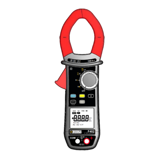
2. PRESENTATION The F402 is a professional electrical measuring instrument that combines the following functions: „ Current measurement, „ Measurement of inrush current / over current (True-Inrush), „ Voltage measurement, „ Frequency measurement, „ Continuity test with buzzer, „ Resistance measurement, „... -
Page 6: The Switch
2.1. THE SWITCH The switch has five positions. To access the , functions, set the switch to the desired function. Each setting is confirmed by an audible signal. The functions are described in the table below: Figure 2: the switch Item Function See §... -
Page 7: The Keys Of The Keypad
2.2. THE KEYS OF THE KEYPAD Here are the five keys of the keypad: Figure 3: the keys of the keypad Item Function See § Storage of values, disabling of display Compensation of the resistance of the leads in the continuity and 4.6.1 ohmmeter function Selection of the type of measurement (AC, DC) -
Page 8: The Display Unit
2.3. THE DISPLAY UNIT Here is the display unit of the clamp multimeter: HOLD kΩ MAX MIN AC DC °C°F Figure 4: the display unit Item Function See § Display of the modes selected (keys) Display of the measurement value and unit 4.12 Display of the MAX/MIN modes Type of measurement (AC or DC) -
Page 9: The Terminals
2.3.1. THE SYMBOLS OF THE DISPLAY UNIT Symbol Designation Alternating current or voltage Direct current or voltage Storage of the values and hold of the display HOLD Maximum RMS value Minimum RMS value Volt Hertz Ampere Ω Milli-prefix Kilo-prefix Compensation of the resistance of the leads Continuity test Diode test Permanent display (automatic switching off de-activated) -
Page 10: The Keys
3. THE KEYS The keys of the keypad respond differently to short, long, and sustained presses. keys provide new functions and allow the detection and acquisition of parameters complementary to the MAX/MIN usual elementary measurements. Each of these keys can be used independently of the others or in perfect complementarity with them: this makes navigation simple and intuitive for looking up all measurement results. -
Page 11: Key (Second Function)
3.2. KEY (SECOND FUNCTION) This key is used to select the type of measurement (AC, DC) and the second functions marked in yellow next to the relevant positions of the switch. It can also be used, in the configuration mode, to modify the default value (see § 4.4). Remark: the key is invalid in the MAX/MIN and HOLD modes. -
Page 12: Hz Key
3.4.2. THE MAX/MIN MODE + ACTIVATION OF THE HOLD MODE ... serve Successive presses on MAX/MIN - to display successively the MAX/MIN values detected before the short HOLD key was pressed. Note: the HOLD function does not interrupt the acquisition of new MAX, MIN values. 3.4.3. -
Page 13: Use
4. USE 4.1. COMMISSIONING Insert the batteries supplied with the device as follows: 1. Using a screwdriver, unscrew the screw of the battery compartment cover (item 1) on the back of the housing and open it ; 2. Place the 4 batteries in the compartment (item 2), taking care to get the polarities right ; 3. - Page 14 4.4.2. DE-ACTIVATION OF AUTOMATIC SWITCHING OFF (AUTO POWER OFF) To de-activate automatic switching off: HOLD 1. In the OFF position, hold the key down while turning the switch to , until the "full screen" display ends and a beep is emitted, to enter the configuration mode. The symbol is displayed.
-
Page 15: Voltage Measurement (V)
4.5. VOLTAGE MEASUREMENT (V) To measure a voltage, proceed as follows: 1. Set the switch to 2. Connect the black lead to the COM terminal and the red lead to "+", 3. Place the test probes or the crocodile clips on the terminals of the circuit to be measured. The device selects AC or DC automatically according to which measured value is larger. -
Page 16: Resistance Measurement Ω
4.7. RESISTANCE MEASUREMENT Ω Warning: Before making a resistance measurement, make sure that the circuit is cold and any capacitors have been discharged. 1. Set the switch to and press the key. The Ω symbol is displayed. 2. Connect the black lead to the "COM" terminal and the red lead to "+". 3. -
Page 17: Starting Current Or Over-Current (True Inrush) Measurement
4.9.1. AC MEASUREMENT For an AC current measurement, proceed as follows: 1. Set the switch to 2. Encircle only the conductor concerned with the clamp. The measured value is displayed on the screen. 4.10. STARTING CURRENT OR OVER-CURRENT (TRUE INRUSH) MEASUREMENT To measure a starting current or over current, proceed as follows: 1. -
Page 18: Frequency Measurement (Hz)
4.11. FREQUENCY MEASUREMENT (Hz) The frequency measurement is available in V and A for AC quantities. The measurement is based on a count of the passages of the signal through zero (positive-going edges). 4.11.1. FREQUENCY MEASUREMENT IN VOLTAGE To measure the frequency in voltage, proceed as follows: 1. -
Page 19: Temperature Measurement
4.12. TEMPERATURE MEASUREMENT 4.12.1. MEASUREMENT WITHOUT EXTENAL SENSOR 1. Set the switch to The temperature displayed (blinking) is the internal temeprature of the device, equal to the ambient temperature after a sufficiently long thermal stabilization time (at least one hour). 4.12.2. -
Page 20: Characteristics
5. CHARACTERISTICS 5.1. REFERENCE CONDITIONS Quantities of influence Reference conditions Temperature 23°C ± 2°C Relative humidity 45 % to 75 % Supply voltage 6.0 V ± 0.5 V Frequency range of the applied signal 45 - 65 Hz Sine wave pure Peak factor of the applied alternating signal √... - Page 21 5.2.3. AC CURRENT MEASUREMENT Measurement range (2) 0.25 A to 99.99 A 100.0 A to 999.9 A 1 000 A (1 500 A peak) (1) Specified measurement range 0 to 100 % of the measurement range Uncertainties ± (1 % R + 10 pts) ±...
- Page 22 5.2.7. DIODE TEST Measurement range 0.000 V to 3.199 VDC Specified measurement range 1 to 100 % of the measurement range Uncertainties ± (1 % R + 10 pts) Resolution 0.001 V Measurement current 0.55 mA Indication: junction reversed or open-circuit Display of "OL"...
-
Page 23: Environmental Conditions
5.3. ENVIRONMENTAL CONDITIONS Environmental conditions in use in storage Temperature - 20°C to + 55°C - 40°C to + 70°C Relative humidity (RH) ≤ 90 % to 55°C ≤ 90 % up to 70°C 5.4. CHARACTERISTICS OF CONSTRUCTION Housing Rigid polycarbonate shell with moulded elastomer covering Polycarbonate Jaws Opening: 48 mm... -
Page 24: Variations In The Domain Of Use
5.7. VARIATIONS IN THE DOMAIN OF USE Influence Quantity of influence Range influence Quantity influenced Typical 0.1 % R / 10°C 0.1 % R / 10°C 0.5 % R / 10°C + 2 pts Temperature - 20 ... + 55°C 1 % R / 10°C* 1.5 % R / 10°C + 2 pts* Ω... -
Page 25: Maintenance
6. MAINTENANCE The instrument has no parts that can be replaced by personnel who are not trained and approved. Any non-approved repair or other work, or replacement of a part by an "equivalent", may severely compromise safety. 6.1. CLEANING „ Disconnect everything connected to the device and set the switch to OFF. „... - Page 26 FRANCE INTERNATIONAL Chauvin Arnoux Chauvin Arnoux 12-16 rue Sarah Bernhardt Tél : +33 1 44 85 44 38 92600 Asnières-sur-Seine Fax : +33 1 46 27 95 69 Tél : +33 1 44 85 44 85 Fax : +33 1 46 27 73 89 Our international contacts info@chauvin-arnoux.com...
Need help?
Do you have a question about the F402 and is the answer not in the manual?
Questions and answers