Table of Contents
Advertisement
Quick Links
Advertisement
Table of Contents

Related Manuals for Chauvin Arnoux F603


Summary of Contents for Chauvin Arnoux F603
- Page 1 GB - User’s manual F603 Clamp multimeter...
-
Page 2: Table Of Contents
CONTENTS PRESENTATION ......................7 THE SWITCH ........................8 THE KEYS OF THE KEYPAD ..................9 THE DISPLAY UNIT ....................... 10 1.3.1 The symbols of the display unit ..............11 1.3.2 Measurement capacity exceeded (O.L) ............12 THE TERMINALS ......................12 THE KEYS ......................... - Page 3 CURRENT MEASUREMENT (A) ................. 24 3.9.1 AC measurement ..................25 3.9.2 DC measurement ..................25 3.10 STARTING CURRENT OR OVERCURRENT (TRUE INRUSH) MEASUREMENT ............................. 26 3.11 FREQUENCY MEASUREMENT (H ) ................. 27 3.11.1 Frequency measurement in voltage.............. 27 3.11.2 Frequency measurement in current.............. 27 3.12 TEMPERATURE MEASUREMENT ................
- Page 4 You have just acquired an F603 clamp multimeter and we thank you. For best results from your device : • read this user manual attentively, • observe the precautions for its use. Meanings of the symbols used on the device Danger.
- Page 5 PRECAUTIONS FOR USE This device complies with safety standards IEC-61010-1 and 61010-2-032 for voltages of 1,000V in category IV at an altitude OF less than 2000m, indoors, with a degree of pollution not exceeding 2. These safety instructions are intended to ensure the safety of persons and proper operation of the device.
- Page 6 As a safety measure, and to avoid repeated overloads on the inputs of the device, we recommend performing configuration operations only when the device is disconnected from all dangerous voltages. MEASUREMENT CATEGORIES Definitions of the measurement categories : CAT II: Circuits directly connected to the low-voltage installation. Example: power supply to household electrical appliances and portable tools.
-
Page 7: Presentation
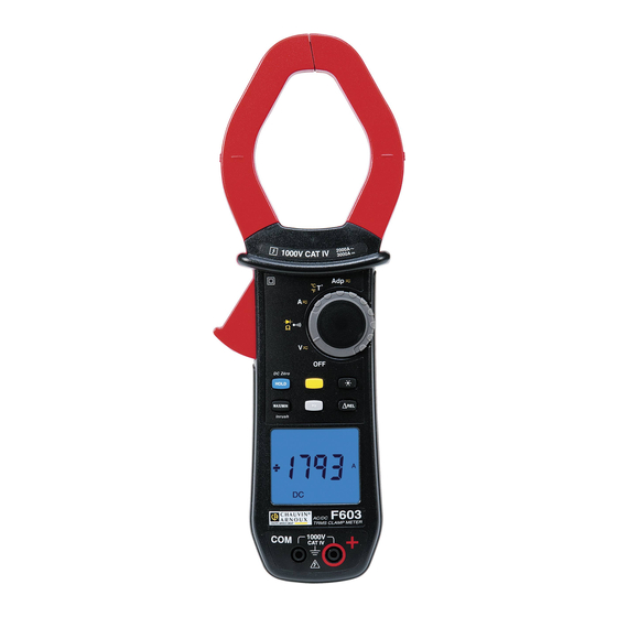
1 PRESENTATION The F603 is a professional electrical measuring instrument that combines the following functions: Current measurement; Measurement of inrush current / overcurrent (True-Inrush); Voltage measurement; Frequency measurement; Continuity test with buzzer; Resistance measurement;... -
Page 8: The Switch
THE SWITCH The switch has six positions. To access the , functions, set the switch to the desired function. Each setting is confirmed by an audible signal. The functions are described in the table below. Figure 2 : the switch Item Function See §... -
Page 9: The Keys Of The Keypad
THE KEYS OF THE KEYPAD Here are the six keys of the keypad : Figure 3 : the keys of the keypad Item Function See § Storage of values, disabling of display Zero correction A 3.9.2 Compensation of the resistance of the leads in the 3.6.1 continuity and ohmmeter function Selection of the type of measurement (AC, DC) -
Page 10: The Display Unit
THE DISPLAY UNIT Here is the display unit of the clamp multimeter: Figure 4 : the display unit Item Function See § Display of the modes selected (keys) Display of the measurement value and unit 3.12 Display of the MAX/MIN modes Type of measurement (AC or DC) Display of the selected modes (switch) Spent battery indication... -
Page 11: The Symbols Of The Display Unit
1.3.1 The symbols of the display unit Symbol Designation Alternating current or voltage Direct current or voltage ∆REL Relative value, with respect to a reference ∆Ref Reference value Storage of the values and hold of the display Maximum RMS value Minimum RMS value Volt Hertz... -
Page 12: Measurement Capacity Exceeded (O.l)
1.3.2 Measurement capacity exceeded (O.L) The O.L (Over Load) symbol is displayed when the display capacity is exceeded. THE TERMINALS The terminals are used as follows: Figure 5 : the terminals Item Function Cold terminal (COM) Hot terminal (+) -
Page 13: The Keys
2 THE KEYS The keys of the keypad respond differently to short, long, and sustained presses. , and keys provide new functions and allow the detection and acquisition of parameters complementary to the usual elementary measurements. Each of these keys can be used independently of the others or in perfect complementarity with them: this makes navigation simple and intuitive for looking up all measurement results. -
Page 14: Key (Second Function)
See also § 2.4.2 and § 2.5.2 for the action key with the action of the and with the action of the key. KEY (SECOND FUNCTION) This key is used to select the type of measurement (AC, DC) and the second functions marked in yellow next to the relevant positions of the switch. -
Page 15: Key
2.4.1 In the normal mode This key activates detection of the MAX and MIN values of the measurements made. Max and Min are the extreme mean values in DC and the extreme RMS values in AC. R emark : in this mode, the "automatic switching off" function of the device is automatically de-activated. -
Page 16: Access To The True-Inrush Mode ( Set To )
2.4.3 Access to the True-INRUSH mode ( set to This key allows measurement of the True-Inrush current (starting current, or overcurrent in steady-state operation) for AC or DC current. Successive …serves presses on to enter the True-INRUSH mode long (>2 sec) -"Inrh"... -
Page 17: The Hz Function + Activation Of The Hold Mode
2.5.2 The Hz function + activation of the HOLD mode Successive …serves presses on -to store the frequency -to display successively the stored frequency, then the voltage or the current This key is used to display and store the reference value or to display the differential and relative values in the unit of magnitude measured or in %. -
Page 18: Use
3 USE COMMISSIONING Insert the batteries supplied with the device as follows: Using a screwdriver, unscrew the screw of the battery compartment cover (item 1) on the back of the housing and open it. Place the 4 batteries in the compartment (item 2), taking care to get the polarities right. -
Page 19: Switching The Clamp Multimeter
SWITCHING THE CLAMP MULTIMETER The clamp multimeter can be switched off either manually, by setting the switch to OFF, or automatically, after ten minutes with no action on the switch and/or the keys. Thirty (30) seconds before the device is switched off, an audible signal sounds intermittently. -
Page 20: Programming Of The Current Threshold For The True Inrush Measurement
3.4.3 Programming of the current threshold for the True INRUSH measurement To program the triggering current threshold of the True INRUSH measurement: 1. in the OFF position, hold the key down while turning the switch to , until the "full screen" display ends and a beep is emitted, to enter the configuration mode. -
Page 21: Programming Of The Adapter Function Scale Factor
3.4.5 Programming of the Adapter function scale factor To program the Adapter function scale factor : From the OFF position, hold the key down while turning the switch until the "full screen" display ends and a beep is emitted, to enter configuration mode. -
Page 22: Continuity Test
The measured value is displayed on the screen. CONTINUITY TEST Warning : Before performing the test, make sure that the circuit is off and any capacitors have been discharged. Set the switch to ; the symbol is displayed ; Connect the black lead to the COM terminal and the red lead to «+». Place the test probes or the crocodile clips on the terminals of the circuit or component to be tested. -
Page 23: Automatic Compensation Of The Resistance Of The Leads
3.6.1 Automatic compensation of the resistance of the leads Warning : before the compensation is executed, the MAX/MIN and HOLD modes must be de-activated. To perform automatic compensation of the resistance of the leads, proceed as follows: Short-circuit the leads connected to the device. Hold the key down until the display unit indicates the lowest value. -
Page 24: Diode Test
DIODE TEST Warning: Before performing the diode test, make sure that the circuit is cold and any capacitors have been discharged. Set the switch to and press the key twice. The symbol is displayed. Connect the black lead to the COM terminal and the red lead to «+». Place the test probes or the crocodile clips on the terminals of the component to be tested. -
Page 25: Ac Measurement
3.9.1 AC measurement For an AC current measurement, proceed as follows: Set the switch to and select AC by pressing the key. The AC symbol is displayed. Encircle only the conductor concerned with the clamp. The device selects AC or DC automatically; The measured value is displayed on the screen. -
Page 26: Starting Current Or Overcurrent (True Inrush) Measurement
The measurement is displayed on screen. 3.10 STARTING CURRENT OR OVERCURRENT (TRUE INRUSH) MEASUREMENT Remark : the measurement can be made only in AC or DC mode. To measure a starting current or overcurrent, proceed as follows: Set the switch to , correct the DC zero (§... -
Page 27: Frequency Measurement (Hz)
3.11 FREQUENCY MEASUREMENT (HZ) The frequency measurement is available in V and A for AC quantities. The measurement is based on a count of the passages of the signal through zero (positive-going edges). 3.11.1 Frequency measurement in voltage To measure the frequency in voltage, proceed as follows: Set the switch to and press the key. -
Page 28: Temperature Measurement
The measured value is displayed on the screen. 3.12 TEMPERATURE MEASUREMENT 3.12.1 Measurement without external sensor Set the switch to The temperature displayed (blinking) is the internal temperature of the device, equal to the ambient temperature after a sufficiently long thermal stabilization time (at least one hour). -
Page 29: Adapter Function Measurement
The temperature is displayed on the screen. To change the unit, °F or °C, press the key. Remarks : If the external sensor is defective, the temperature displayed blinks. If there are large variations of the environment of the device, the measurement must be preceded by a stabilization time. - Page 30 1000 mV/A (1 mV/mA) 10 mV/mA 10 m 100 mV/mA 100 m The example given in Amperes (A) is valid for any other quantity: humidity (%RH), illumination (lux), speed (m/s), etc. Connect the black lead to the COM terminal and the red lead to « + » ; Set the switch to ;...
-
Page 31: Characteristics
4 CHARACTERISTICS REFERENCE CONDITIONS Quantities of influence Reference conditions Temperature 23°C ±2°C Relative humidity 45% to 75% Supply voltage 6.0V ±0.5V Frequency range of the applied signal 45–65Hz Sine wave pure √2 Peak factor of the applied alternating signal Position of the conductor in the clamp centred Adjacent conductors none... -
Page 32: Ac Voltage Measurement
Note (1) The display indicates "+OL" above + 2 000 V and "-OL" below – 2 000 V, in REL mode. The "-" and "+" signs are managed. Above 1000V, a repetitive beep indicates that the voltage being measured is greater than the safety voltage for which the device is guaranteed. 4.2.2 AC voltage measurement Measurement... -
Page 33: Dc Current Measurement
4.2.3 DC current measurement Measurement 0.00 A to 100.0 A to 1 000 A to 3 000 A (1) Range (2) 99.99 A 999.9 A Specified 0 to 100% of the measurement range measurement range until 2 000 A ± (1,5% L +3 pt) from 2 000 A Uncertainties (2) ±... -
Page 34: True-Inrush Measurement
4.2.5 True-Inrush measurement Measurement range 20 A to 2000 A AC 20 A to 3000 A DC Specified 0 to 100% of the measurement range measurement range Uncertainties ± (5% L + 5 pt) Resolution Specific characteristics in PEAK mode in True-Inrush (from 10Hz to 1 kHz in AC): •... -
Page 35: Diode Test
4.2.8 Diode test Measurement range 0.000V to 3.199V DC Specified measurement range 1 to 100% of the measurement range Uncertainties ± (1% R + 10 pt) Resolution 0.001V Measurement current 0.55 mA Indication: junction reversed or Display of "OL" when the measured open-circuit voltage >3.199V ... -
Page 36: Temperature Measurement
4.2.10 Temperature measurement Function External temperature Type of sensor K thermocouple Measurement range -60.0°C to +999.9°C +1000°C to +1200°C -76.0°F to +1831.8°F +1832°F to +2192°F Specified measurement 1 to 100% of the 0 to 100% of the range measurement range measurement range Uncertainties (1) 1% R ±3°C... -
Page 37: Environmental Conditions
4.2.11.2 In AC mode Measurement range (1) 5.0-999.9 mV 1.00-9.99 V Specified measurement 1 to 100% of the 0 to 100% of the range (2) measurement range measurement range 5.0 mV to 99.9 mV 1% L +3pt ± (1% L + 10 pt) Uncertainties 100.0 mV to 999.9 mV ±... -
Page 38: Characteristics Of Construction
CHARACTERISTICS OF CONSTRUCTION Housing Rigid polycarbonate shell with moulded elastomer covering Polycarbonate Jaws Opening: 60 mm Clamping diameter: 60 mm LCD display unit Screen Blue backlighting Dimension: 41x48 mm Dimension H-296 x W-111 x D-41 mm Weight 640g (with the batteries) -
Page 39: Power Supply
POWER SUPPLY Batteries 4x1,5V LR6 Mean life >350 hours (without backlighting) Duration of operation before After 10 minutes without action on the switch automatic switching off and/or keys COMPLIANCE WITH INTERNATIONAL STANDARDS Compliant with standards IEC-61010-1, IEC-61010-2- 30, and IEC-61010-2-32: Electric safety 1000V CAT-IV. -
Page 40: Variations In The Domain Of Use
VARIATIONS IN THE DOMAIN OF USE Influence Quantity of Quantity Range of influence influence influenced Typical V AC 0,1%R/10°C V DC 0,1%R/10°C 0,5%R/10°C + 2 pt Temperature -20...+55°C 1%R/10°C* 1,5%R/10°C + 2pt* T°C (0,2%R+1°C)/10°C (0,3%R+2°C)/10°C 0,1%R/10°C + 2pt Hz Ω 0,1%R/10°C + 3pt Humidity 10%...90%RH... -
Page 41: Maintenance
5 MAINTENANCE The instrument has no parts that can be replaced by personnel who are not trained and approved. Any non-approved repair or other work, or replacement of a part by an "equivalent", may severely compromise safety. CLEANING • Disconnect everything connected to the device and set the switch to OFF. •... -
Page 42: Warranty
• Damage caused by shocks, falls, or floods. 7 DELIVERY CONDITION The F603 clamp multimeter is delivered in its packaging box with : • 2 banana-banana leads, one red and one black •...
Need help?
Do you have a question about the F603 and is the answer not in the manual?
Questions and answers