Table of Contents
Advertisement
Quick Links
Advertisement
Table of Contents

Subscribe to Our Youtube Channel
Related Manuals for Chauvin Arnoux F403


Summary of Contents for Chauvin Arnoux F403
- Page 1 CLAMP MULTIMETER F403 User’s manual EN G LI S H...
-
Page 2: Table Of Contents
CONTENTS PRESENTATION ......................7 THE SWITCH ........................8 THE KEYS OF THE KEYPAD ..................9 THE DISPLAY UNIT ....................... 10 1.3.1 The symbols of the display unit ..............11 1.3.2 Measurement capacity exceeded (O.L) ............12 THE TERMINALS ......................12 THE KEYS ......................... - Page 3 CURRENT MEASUREMENT (A) ................. 24 3.9.1 AC measurement ..................24 3.9.2 DC measurement ..................25 3.10 STARTING CURRENT OR OVERCURRENT (TRUE INRUSH) MEASUREMENT ......................... 26 3.11 FREQUENCY MEASUREMENT (H ) ................. 26 3.11.1 Frequency measurement in voltage.............. 27 3.11.2 Frequency measurement in current.............. 27 3.12 TEMPERATURE MEASUREMENT ................
- Page 4 You have just acquired an F403 clamp multimeter and we thank you. For best results from your device : read this user manual attentively, • observe the precautions for its use. • Meanings of the s ymbols us ed on the devic e Danger.
- Page 5 PRECAUTIONS FOR USE This device complies with safety standards IEC-61010-1 and 61010-2-032 for voltages of 1,000V in category IV at an altitude OF less than 2000m, indoors, with a degree of pollution not exceeding 2. These safety instructions are intended to ensure the safety of persons and proper operation of the device.
- Page 6 As a safety measure, and to avoid repeated overloads on the inputs of the device, we recommend performing configuration operations only when the device is disconnected from all dangerous voltages. MEASUREMENT CATEGORIES Definitions of the measurement categories : CAT II: Circuits directly connected to the low-voltage installation. Example: power supply to household electrical appliances and portable tools.
-
Page 7: Presentation
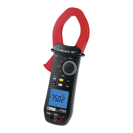
PRESENTATION The F403 is a professional electrical measuring instrument that combines the following functions: Current measurement; Measurement of inrush current / overcurrent (True-Inrush); Voltage measurement; Frequency measurement; Continuity test with buzzer; Resistance measurement; Diode test;... -
Page 8: The Switch
THE SWITCH The switch has six positions. To access the , functions, set the switch to the desired function. Each setting is confirmed by an audible signal. The functions are described in the table below. Figure 2 : the switch Item Function See §... -
Page 9: The Keys Of The Keypad
THE KEYS OF THE KEYPAD Here are the six keys of the keypad : Figure 3 : the keys of the keypad Item Function See § Storage of values, disabling of display Zero correction A 3.9.2 Compensation of the resistance of the leads in the 3.6.1 continuity and ohmmeter function Selection of the type of measurement (AC, DC) -
Page 10: The Display Unit
THE DISPLAY UNIT Here is the display unit of the clamp multimeter: Figure 4 : the display unit Item Function See § Display of the modes selected (keys) Display of the measurement value and unit 3.12 Display of the MAX/MIN modes Type of measurement (AC or DC) Display of the selected modes (switch) Spent battery indication... -
Page 11: The Symbols Of The Display Unit
1.3.1 The symbols of the display unit Symbol Designation Alternating current or voltage Direct current or voltage Relative value, with respect to a reference ∆REL Reference value ∆Ref Storage of the values and hold of the display Maximum RMS value Minimum RMS value Volt Hertz... -
Page 12: Measurement Capacity Exceeded (O.l)
1.3.2 Measurement capacity exceeded (O.L) The O.L (Over Load) symbol is displayed when the display capacity is exceeded. THE TERMINALS The terminals are used as follows: Figure 5 : the terminals Item Function Cold terminal (COM) Hot terminal (+) 2 THE KEYS The keys of the keypad respond differently to short, long, and sustained presses. -
Page 13: Key
This key is used to: store and look up the last values acquired specific to each function (V, A, Ω, T°, Adp) according to the specific modes previously activated (MAX/MIN, Hz, ΔREL); the present display is then maintained while the detection and acquisition of new values continues;... -
Page 14: Key
Remark: the key is invalid in the MAX/MIN, HOLD and ΔREL modes. Successive … serve presses on -to select AC or DC. Depending on your choice, the screen displays AC or DC -to cycle through the Ω and diode test modes and to return to the continuity test -to select °C or °F as the unit This key is used to backlight the display unit. -
Page 15: The Max/Min Mode + Activation Of The Hold Mode
Successive presses on … serve -to activate detection of the MAX/MIN values -to display the MAX or MIN value successively -to return to display of the present measurement without exiting from the mode (the values already detected are not erased) short R emark: the MAX and MIN symbols are both displayed,... -
Page 16: Key
long (>2 sec) to enter the True-INRUSH mode -"Inrh" is displayed for 3s (the backlighting blinks) -the triggering threshold is displayed for 5s (the backlighting is steady); -"------" is displayed and the "A" symbol flashes -after detection and acquisition, the inrush current measurement is displayed, after the calculations stage "------"... -
Page 17: Key
-to store the frequency -to display successively the stored frequency, then the voltage or the current This key is used to display and store the reference value in the unit of magnitude measured, or to display the differential and relative values, in %. Successive …serve presses on... -
Page 18: Use
3 USE COMMISSIONING Insert the batteries supplied with the device as follows: Using a screwdriver, unscrew the screw of the battery compartment cover (item 1) on the back of the housing and open it. Place the 4 batteries in the compartment (item 2), taking care to get the polarities right. -
Page 19: Configuration
keys. Thirty (30) seconds before the device is switched off, an audible signal sounds intermittently. To re-activate the device, press any key or turn the switch. CONFIGURATION As a safety measure, and to avoid repeated overloads on the inputs of the device, we recommend performing configuration operations only when the device is disconnected from all dangerous voltages. -
Page 20: Change Of Temperature Measurement Unit
1. in the OFF position, hold the key down while turning the switch to , until the "full screen" display ends and a beep is emitted, to enter the configuration mode. The display unit indicates the percentage overshoot to apply to the measured current to determine the measurement triggering threshold. -
Page 21: Programming Of The Adapter Function Scale Factor
3.4.5 Programming of the Adapter function scale factor To program the Adapter function scale factor : From the OFF position, hold the key down while turning the switch until the "full screen" display ends and a beep is emitted, to enter configuration mode. -
Page 22: Continuity Test
The measured value is displayed on the screen. CONTINUITY TEST Warning : Before performing the test, make sure that the circuit is off and any capacitors have been discharged. Set the switch to ; the symbol is displayed ; Connect the black lead to the COM terminal and the red lead to «+». Place the test probes or the crocodile clips on the terminals of the circuit or component to be tested. -
Page 23: Automatic Compensation Of The Resistance Of The Leads
3.6.1 Automatic compensation of the resistance of the leads Warning : before the compensation is executed, the MAX/MIN and HOLD modes must be de-activated. To perform automatic compensation of the resistance of the leads, proceed as follows: Short-circuit the leads connected to the device. Hold the key down until the display unit indicates the lowest value. -
Page 24: Diode Test
DIODE TEST Warning: Before performing the diode test, make sure that the circuit is cold and any capacitors have been discharged. Set the switch to and press the key twice. The symbol is displayed. Connect the black lead to the COM terminal and the red lead to «+». Place the test probes or the crocodile clips on the terminals of the component to be tested. -
Page 25: Dc Measurement
Encircle only the conductor concerned with the clamp. The device selects AC or DC automatically; The measured value is displayed on the screen. 3.9.2 DC measurement To measure the DC current, if the display unit does not indicate "0", first correct the DC zero as follows: Step 1 : to correct the DC zero Important : The clamp must not be closed on the conductor during the DC zero... -
Page 26: Starting Current Or Overcurrent (True Inrush) Measurement
The measurement is displayed on screen. 3.10 STARTING CURRENT OR OVERCURRENT (TRUE INRUSH) MEASUREMENT Remark : the measurement can be made only in AC or DC mode. To measure a starting current or overcurrent, proceed as follows: Set the switch to , correct the DC zero (§... -
Page 27: Frequency Measurement In Voltage
3.11.1 Frequency measurement in voltage To measure the frequency in voltage, proceed as follows: Set the switch to and press the key. The Hz symbol is displayed. Select AC by pressing the yellow key until the desired choice is reached. Connect the black lead to the COM terminal and the red lead to “+”. - Page 28 The measured value is displayed on the screen.
-
Page 29: Temperature Measurement
3.12 TEMPERATURE MEASUREMENT 3.12.1 Measurement without external sensor Set the switch to The temperature displayed (blinking) is the internal temperature of the device, equal to the ambient temperature after a sufficiently long thermal stabilization time (at least one hour). 3.12.2 Measurement with external sensor The device measures the temperature using a K thermocouple. -
Page 30: Adapter Function Measurement
3.13 ADAPTER FUNCTION MEASUREMENT This function makes it possible to connect any adapter/sensor whatever that converts an electrical or physical quantity into a DC or AC voltage, and obtain a direct, immediate reading without applying a conversion factor. The mode, AC or DC (the default), must be chosen manually using the yellow key. The measurement is made as a voltage measurement. -
Page 31: Characteristics
The value of the measurement is displayed on screen. 4 CHARACTERISTICS REFERENCE CONDITIONS Quantities of influence Reference conditions Temperature: 23°C ±2°C Relative humidity: 45% to 75% Supply voltage: 6.0V ±0.5V Frequency range of the applied signal: 45–65Hz Sine wave: pure Peak factor of the applied alternating signal: √2 Position of the conductor in the clamp:... -
Page 32: Dc Voltage Measurement
4.2.1 DC voltage measurement Measurement range 0.00V to 99.99V 100.0V to 999.9V 1000V (1) Specified 0 to 100% of the 0 to 100% of the measurement range measurement range measurement range from 0.00V to 9.99V ±(1% R + 10 pt) Uncertainties from 10.00V to ±(1% R +3 pt) -
Page 33: Dc Current Measurement
4.2.3 DC current measurement Measurement 0.00 A to 100.0 A to 1 000 A to 1 500 A Range (2) 99.99 A 999.9 A Specified 0 to 100% of the measurement range measurement range Uncertainties (2) ± (1% L + 10 ±... -
Page 34: Continuity Measurement
Specific characteristics in PEAK mode in True-Inrush (from 10Hz to 1 kHz in AC): • Uncertainties: add ± (1.5% L+0.5A) to the values in the tables above. • PEAK capture time: 1ms min. to 1.5ms max. 4.2.6 Continuity measurement Measurement range 0.0Ω... -
Page 35: Frequency Measurements
Indication: junction reversed or Display of "OL" when the measured open-circuit voltage >3.199V Note : The "-" sign is disabled for the diode test function. 4.2.9 Frequency measurements 4.2.9.1 C harac teris tic s in voltage 5.0 Hz to 1000 Hz to 10.00 kHz to Measurement range (1) -
Page 36: Adapter Function Measurement
Uncertainties (1) 1% R ±3°C 1% R ±3°C 1% R ±5.4°F 1% R ±5.4°F Resolution 0.1°C 1°C 0.1°F 1°F Note (1) - The stated external temperature measurement accuracy does not take the accuracy of the K thermocouple into account. Note 2 - use of the thermal time constant (0.7min/°C): - If there is a sudden variation of the temperature of the clamp, by 10°C for example, the clamp will be at 99% (cnst= 5) of the final temperature after 0.7min/°Cx10°Cx5= 35 min (to which must be added the constant of the... -
Page 37: Environmental Conditions
• In DC, the display indicates "+OL" above +9999 points and "- OL" below -9999 points. The "-" and "+" signs are managed (polarity). • In AC, the display indicates "OL" above 9999 points. Note (2) - the max. bandwidth is 1kHz. Specific characteristics in MAX/MIN mode (from 10Hz to 1kHz): •... -
Page 38: Compliance With International Standards
COMPLIANCE WITH INTERNATIONAL STANDARDS Compliant with standards IEC-61010-1, IEC-61010-2- 30, and IEC-61010-2-32: Electric safety: 1000V CAT-IV. Compliant with standard EN-61326-1 Electromagnetic Classification: residential environment compatibility: Mechanical Free fall: 2m (in accordance with standard IEC-68-2-32) strength: Housing: IP54 (per standard IEC-60529) Level of protection of the housing: Jaws: IP40... -
Page 39: Maintenance
Application of a 0-1000V DC or voltage on the 3% R + 1 pt < 1 pt clamp 1.4 to 3.5, limited A (AC) peak factor to 1500 A peak 3% R + 1 pt V (AC) 1400V peak Note* in Temperature : Influence specified until 1000 A DC 5 MAINTENANCE The instrument has no parts that can be replaced by personnel who are not trained and approved. -
Page 40: Metrological Check
This instrument should be checked at least once a year. For checks and calibrations, contact one of our accredited metrology laboratories (information and contact details available on request), at our Chauvin Arnoux subsidiary or the branch in your country. REPAIR For all repairs before or after expiry of warranty, please return the device to your distributor. -
Page 41: Delivery Condition
7 DELIVERY CONDITION The F403 clamp multimeter is delivered in its packaging box with : 2 banana-banana leads, one red and one black • 2 test probes, one red and one black • 1 K thermocouple with banana terminations •... - Page 42 Tel: 01 61 61 961-0 - Fax: 01 61 61 961-61 Tel: (01) 89 04 25 - Fax: (01) 89 04 24 SCANDINAVIA - CA Mätsystem AB USA - Chauvin Arnoux Inc - d.b.a AEMC Instruments 200 Foxborough Blvd. - Foxborough - MA 02035 Sjöflygvägen 35 - SE 18304 TÄBY...
Need help?
Do you have a question about the F403 and is the answer not in the manual?
Questions and answers