Table of Contents
Advertisement
Quick Links
Download this manual
See also:
User Manual
Advertisement
Table of Contents

Subscribe to Our Youtube Channel
Related Manuals for Chauvin Arnoux F 03


Summary of Contents for Chauvin Arnoux F 03
- Page 1 F 03 Pince multimètre Clamp multimeter Vielfachmesszange Pinza multimetro Pinza multimetrica F R A N Ç A I S Notice de fonctionnement E N G L I S H User's manual D E U T S C H Bedienungsanleitung I T A L I A N O Libretto d’Istruzioni...
- Page 2 English Meaning of symbol Caution! Please consult the User Manual before using the device. In this User Manual, failure to follow or carry out instructions preceded by this symbol may result in personal injury or damage to the device and the installations. Meaning of symbol This appliance is protected by double insulation or reinforced insulation.
-
Page 3: Table Of Contents
CONTENTS PRESENTATION ..............23 DESCRIPTION ............... 23 IMPLEMENTATION FUNCTIONAL CHARACTERISTICS ........27 3.1 Reference conditions ............27 3.2 Voltage measurements (V) .......... 27 3.3 Audio continuity test ( ) ..........28 3.4 Resistance measurement (Ω) .......... 29 3.5 Semi-conductor test ( ) .......... -
Page 4: Presentation
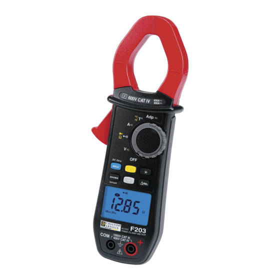
1. PRESENTATION Reliability and simplicity are the key features of the F03 multimeter clamp for use by electricity professionals: A compact instrument integrating a current sensor for measuring intensity without switching off the power to the circuit to be checked. Exceptional ergonomic design which includes: - automatic or manual selection of the type of signal to be measured, direct or alternating,... - Page 5 Key held down It enables the user to enter a measurement or operating mode and to stay in this mode while the key is held down. When the key is released, the user reverts to the previous mode used. HOLD has 4 different functions (see description § 3.8) - Blocking the display - Preselection of MIN/MAX mode - Automatic offset of lead resistance...
- Page 6 Liquid crystal display The liquid crystal display provides a digital display of the values measured and the associated units and symbols. Digital display 4 digits, 9999 points, 3 decimal points, + and - signs (DC and peak measurement). + OL : Outside the range by a positive value (> 3999 points) - OL : Outside the range by a negative value : Outside the range by a value without a sign...
- Page 7 EXT Measurement of temperature when the thermocouple is connected Test of semi-conductors on Ω Ω Ω Ω Ω position The Buzzer The buzzer makes different sounds according to the function assigned. - Short and medium buzz: valid key - Short and high-pitched buzz: invalid key - Short and low-pitched buzz: exit from MIN/MAX mode - 2 short, high-pitched buzzes: validation of a configuration parameter...
-
Page 8: Implementation Functional Characteristics
3. IMPLEMENTATION FUNCTIONAL CHARACTERISTICS 3.1 Reference conditions The functional characteristics mentioned in each of the measurement functions are guaranteed within the following reference conditions: - Temperature: +23°C ±3 K. - Humidity ratio: 45% to 75% relative humidity. - Supply voltage: 8.5 V ±0.5 V. - Frequency range of the alternating signal applied: 45 -65 - Peak factor of the alternating signal applied: √... -
Page 9: Audio Continuity Test
MIN/ MAX Mode: - Accuracy: ditto preceding table + 0.2% L - Capture time: 100 ms typ. PEAK Mode: - Accuracy: ditto preceding table +2% L - Capture time: 500 µs typ. (2.5 ms max.) Special characteristics in V-Live mode - Detection threshold accuracy: 45 V ±... -
Page 10: Resistance Measurement (Ω)
3.4 Resistance measurement (Ω Ω Ω Ω Ω ) 1. Connect the measuring leads to the instrument’s terminals. 2. Turn the selector switch to the position and press once on the yellow key: symbol is no longer displayed. 3. Connect the instrument to the circuit to be measured. Range selection is automatic. -
Page 11: Current Measurements (A)
3.6 Current measurements 1. Set the selector switch to the "A " position 2. Clamp the conductor through which the current to be measured is passing, ensure that the jaws are properly closed and no foreign body is caught in the space between the jaws. -
Page 12: Temperature Measurement (T°)
3.7 Temperature measurement (T°) 3.7.1 Without a sensor Set the selector switch to the "T°" position. The temperature displayed is the instrument’s internal temperature (the INT symbol is lit), which is the same as the ambient temperature after a sufficient thermal stabilisation time. It can be expressed as °C or °F: the unit is chosen with the yellow key. -
Page 13: Preselection Of Min/Max Mode
3.8.2 Preselection of MIN/MAX mode MIN/MAX mode is preselected by a short press on the HOLD key and then on the MIN/MAX key. MIN/MAX mode is then activated by pressing on the HOLD key. This function allows MIN/MAX mode to be selected when required, to avoid for example, the inclusion of untimely or erroneous MIN/MAX values 3.8.3 Automatic offset of lead resistance... -
Page 14: Saving The Unit (°C Or °F) When Measuring Temperature
3.8.8 Saving the unit (°C or °F) when measuring temperature Hold the yellow key down and turn the selector switch from the OFF to the T° position. The instrument buzzes twice, then the T° symbol lights up and the °F symbol flashes if the instrument was previously in °C or the °C symbol flashes if it was in °F. -
Page 15: Date Of The Instrument's Last Calibration
The default settings are: - Buzzer threshold: 40 Ω - Auto shutdown: with - V-Live function: none - Temperature measurement unit: not managed 3.8.13 Date of the instrument’s last calibration. Hold the MIN/MAX key down and turn the selector switch from the OFF position to the V position. -
Page 16: Environmental Parameters
4.4 Environmental parameters Temperature - Humidity Temperature in °C Reference range Operating range Storage range (without battery) Altitude - Operation: ≤ 2,000 m - Storage ≤ 12.000 m Indoor use Impermeability: protection index IP 40 (according to EN 60529, ed. 92) 4.5 Compliance with norms Electrical safety (as per EN 61010-1 ed. -
Page 17: Variations In Operating Range
4.6 Variations in operating range R e l e v a n t Meas. range Parameter E f f e c t parameter parameter a f f e c t e d T y p i c a l ≤ 1 c t B a t t e r y v o l t a g e 7 . -
Page 18: Operating Limit Conditions
Typical frequency response curve - V = f (f) Specified limits -10% 10000 Hz 10 Hz 100 Hz 1000 Hz Frequency (Hz) - I = f (f) Specified limits 10000 Hz 10 Hz 100 Hz 1000 Hz Frequency (Hz) 4.7 Operating limit conditions Temperature of the conductor clamped: ≤... -
Page 19: To Order
5. TO ORDER Use the descriptions and references given below: F03 ..............P01. 1209.03Z Comes in a blister with a set of two touch leads, 1 x K thermocouple adaptor, 1 x 9 V battery, a carrying case and these operating instructions. F03 .............. -
Page 20: Maintenance
7. MAINTENANCE For maintenance, use only specified spare parts. The manufacturer will not be held responsible for any accident occuring following a repair done other than by its After Sales Service or approved repairers. 7.1 Changing the battery The clamp must be disconnected from any external source of electricity and must not encircle a cable.
Need help?
Do you have a question about the F 03 and is the answer not in the manual?
Questions and answers