Table of Contents
Advertisement
Quick Links
Local air conditioner
Model: GPAC09D
ModelPC08AH-A3NNC4D
Thank you for choosing our product.
For proper operation, please read and keep this manual carefully.
If you have lost the Owner's Manual, please contact the local agent or visit
www.gree.com or sent email to global@gree.com.cn for electronic version.
Advertisement
Table of Contents

Related Manuals for Gree GPAC09D


Summary of Contents for Gree GPAC09D
- Page 1 ModelPC08AH-A3NNC4D Thank you for choosing our product. For proper operation, please read and keep this manual carefully. If you have lost the Owner’s Manual, please contact the local agent or visit www.gree.com or sent email to global@gree.com.cn for electronic version.
-
Page 3: Table Of Contents
Content Operation Notices The Refrigerant ......................1 Operation Environment ....................2 Safety Warning ......................3 Part's Name ......................4 Operation Guide Operation Introduction for Control Panel ..............5 Buttons on Remote Controller .................7 Introduction for Icons on Display Screen ..............7 Introduction for Buttons on Remote Controller ............8 Function Introduction for Combination Buttons ............10 Operation Guide .................... - Page 4 Explanation of Symbols Indicates a hazardous situation that, if not avoided, will DANGER result in death or serious injury. Indicates a hazardous situation that, if not avoided, could WARNING result in death or serious injury. Indicates a hazardous situation that, if not avoided, may CAUTION result in minor or moderate injury.
-
Page 5: The Refrigerant
Appliance filled with flammable gas R32. Before install and use the appliance, read the owner’s manual first. Before repair the appliance, read the service manual first. The Refrigerant To realize the function of the air conditioner unit, a special refrigerant circulates in the system. -
Page 6: Operation Environment
Operation Environment ● The air conditioner must be operated within the temperature range: 16°C ~ 35°C. ● The appliance is for indoor use only. ● The appliance must be positioned so that the plug is accessible. ● This air conditioner can only be used for family, not for commercial industry. -
Page 7: Safety Warning
Safety Warning ● This appliance can be used by children aged from 8 years and above and persons with reduced physical, sensory or mental capabilities or lack of experience and knowledge if they have been given supervision or instruction concerning use of the appliance in a safe way and understand the hazards involved. -
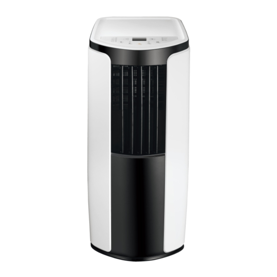
Page 8: Part's Name
Part's Name Controller panel Guide louver Vertical louver Castor Wire-fixing hook Plug of power cord Gastor Air inlet Joint A Heat discharge pipe Joint B+C Remote controller NOTICE: Heat discharge pipe and other installation accessories can't be discarded. -
Page 9: Operation Introduction For Control Panel
Operation Introduction for Control Panel Dual-8 Display Cool mode indicator + / - button Dry mode indicator Fan mode indicator Fan speed indicator Mode button Sleep button Timer button ON/OFF button Fan button Operation of control panel After putting through the power, the air conditioner will give out a sound. After ●... - Page 10 Operation Introduction for Control Panel Mode button Press this button and the mode will circulate according to below sequence: COOL→DRY→FAN COOL: Under this mode, cooling mode indicator is bright. Dual-8 displays set temperature. Temperature setting range is 16°C~30°C. DRY: Under this mode, drying mode indicator is bright. Dual-8 nixie tube won’t display.
-
Page 11: Buttons On Remote Controller
Buttons on Remote Controller ON/OFF button MODE button +/- button FAN button X-FAN button SLEEP button TIMER button Introduction for Icons on Display Screen Timer on Timer off Sending signal X-fan operation Cool operation Sleep operation Dry operation Lock Fan operation Set speed Set temperature Set time... -
Page 12: Introduction For Buttons On Remote Controller
Introduction for Buttons on Remote Controller Note: This is a general use remote controller, it could be used for the air conditioners ● with multifunction; For some function, which the model doesn't have, if press the corresponding button on the remote controller that the unit will keep the original running status. - Page 13 Introduction for Buttons on Remote Controller FAN button Pressing this button can select fan speed circularly as: AUTO, SPEED 1 ( SPEED 2 ( ), SPEED 3 ( AUTO Note: ● Under Auto speed, air conditioner will select proper fan speed automatically according to ambient temperature.
-
Page 14: Function Introduction For Combination Buttons
Introduction for Buttons on Remote Controller Note: ● Timer setting range: 0.5~24h ● The interval between two motions can't exceed 5s, otherwise the remote con- troller will exit setting status. Function Introduction for Combination Buttons Child lock function Pressing “+” and “-” buttons simultaneously can turn on or turn off child lock function. When child lock function is started up, LOCK indicator on remote controller is ON. -
Page 15: Operation Guide
Operation Guide After putting through the power, press "ON/OFF" button on remote controller to turn on the air conditioner. Press "MODE" button to select your required mode: COOL, DRY, FAN. Press "+" or "-" button to set your required temperature. Press "FAN"... -
Page 16: Clean And Maintenance
Clean and Maintenance WARNING ● Before cleaning the air conditioner, please turn off the unit and disconnect power. Otherwise, it may cause electric shock. ● Do not wash air conditioner with water. Otherwise, it may cause electric shock. ● Do not use volatile liquid (such as thinner or gas) to clean the air conditioner. Otherwise, it may damage the appearance of air conditioner. - Page 17 Clean and Maintenance Clean heat discharge pipe Remove the heat discharge pipe from air conditioner, clean and dry it , and then reinstall it. (For the method of installation and removal , please refer to the instruction for "Installation and disassembly of heat discharge pipe"). Checking before use-season 1.
-
Page 18: Malfunction Analysis
Malfunction Analysis Please check below items before asking for maintenance. If the malfunction still can’t be eliminated, please contact local dealer or qualified professionals. Phenomenon Troubleshooting Solution ● Power failure? ● Wait after power recovery. ● Is plug loose? ● Reinsert the plug. ●... - Page 19 Malfunction Analysis Phenomenon Troubleshooting Solution ● Whether air outlet or air inlet is ● Eliminate the obstacles. blocked? ● Under heating mode, whether ● The unit will stop blowing indoor temperature ireaches fan after reaching set set temperature? temperature. ● In order to prevent cold air, No fan blowed ●...
- Page 20 Malfunction Analysis Malfunction code 1. Pour out the water inside chassis. Chassis is full of water. 2. If "H8" still exits, please contact professional person to maintain the unit. Malfunction of ambient Please contact professional person to deal temperature sensor. with it.
-
Page 21: Installation Precaution
Installation Precaution WARNING ● Observe all governing codes and ordinances. ● Do not use damaged or non-standard power cord. ● Be caution during installation and maintenance. Prohibit incorrect operation to prevent electric shock, casualty and other accidents. Selection of installation location Basic requirement Installing the unit in the following places may cause malfuncti on. -
Page 22: Preparation Before Installation
Preparation before Installation Note: check if the accessories are available before installation. Accessory list joint A joint B joint C heat discharge pipe Adapter screw pipe clip rubber plug pipe hoop wire hook battery drainage pipe remote controller (AAA 1.5V) user's manual Tools needed for installation cross screwdriver... -
Page 23: Install Wire Hook
Install Wire Hook ● Assemble the wire hook at the back of the unit with screws (the direction of wire direction of wire hook is upward wire hook screw direction of wire hook is downward ● Wind the power cord around the wire hook. -
Page 24: Removing Collected Water
Removing Collected Water There are 2 ways to remove collected water: Use the continuous drainage option from the bottom hole Note: When using the continuous drainage option from the bottom hole, install drainage pipe before using, otherwise poor drainage will affect normal operation of the unit. - Page 25 Removing Collected Water ■ Drainage way as follows. 1. In cooling or drying operation, the condensation water will be drained to the chassis and spattered by water-striking motor. As the temperature of condenser is high, most of the condensation water will be evaporated and drained to outdoor.
- Page 26 Removing Collected Water Use the continuous drainage option from the middle hole Note: Water can be automatically emptied into a floor drain by attaching 14mm inner diameter hose (not included). 1. Remove the continuous drain cap 1 by turning it counter clockwise then remove the rubber stopper 2 from the spout.
-
Page 27: Installation And Disassembly Of Heat Discharge Pipe
Installation and Disassembly of Heat Discharge Pipe Install heat discharge pipe 1. Rotate joint A and joint B clockwise into the two ends of heat discharge pipe. clockwise joint B+C clockwise heat discharge pipe joint A 2. Insert joint A of heat clasp discharge pipe (the the side with "TOP"... - Page 28 Installation and Disassembly of Heat Discharge Pipe Note of Installingheat discharge pipe correct correct correct wrong ● The length of the heat discharge pipe is less than 1m. It is recommended to use it with shortest length. When installing,heat discharge pipe should be as flat as possible. Don’t prolong the pipe or connect it with other heat discharge pipe.
- Page 29 Installation and Disassembly of Heat Discharge Pipe should not be over 130cm from floor). would easily cause malfunction.) Disassemble heat discharge pipe 1. Remove joint B: 2. Remove joint A: remove joint B from joint C. Press the clasp and lift joint A upwards to remove it.
-
Page 30: Operation Test
● Press mode button to select auto, cooling, drying, fan or heating function, and then check if the unit operates normally. ● If ambient temperature is below 16°C, the unit can't operate in cooling mode. Electric Schematic Diagram GPAC09D POWER BN(BK) ROOM TEMP. - Page 32 2/F, Shing Dao Industrial Building, 232 Aberdeen Main Road, Hong Kong 66129927686...
Need help?
Do you have a question about the GPAC09D and is the answer not in the manual?
Questions and answers