
Related Manuals for Gree GPAC12D


Summary of Contents for Gree GPAC12D
- Page 1 Change for life Owner's Manual Portable Air Conditioner Model: GPAC12D Thank you for choosing our product. Please read this Owner’s Manual carefully before operation and retain it for future reference.
-
Page 3: Table Of Contents
Content Operation Notices Operation Environment ....................1 Safety Warning ......................2 Part's Name ......................3 Operation Guide Introduction for Control Panel ................4 Use of air conditioner .....................6 Using the remote control ..................7 Buttons on Remote Controller .................8 Introduction for Icons on Display Screen ..............8 Introduction for Buttons on Remote Controller ............9 Function Introduction for Combination Buttons .............12 Operation Guide ....................13... - Page 4 Explanation of Symbols Indicates a hazardous situation that, if not avoided, will DANGER result in death or serious injury. Indicates a hazardous situation that, if not avoided, could WARNING result in death or serious injury. Indicates a hazardous situation that, if not avoided, may CAUTION result in minor or moderate injury.
-
Page 5: Operation Environment
Operation Environment ● The air conditioner must be operated within the temperature range: 16°C ~ 35°C. ● The appliance is applied for indoor use only. ● The appliance must be positioned so that the plug is accessible. ● This air conditioner can only be used for domestic, not for commercial industry. -
Page 6: Safety Warning
Safety Warning ● This appliance can be used by children aged from 8 years and above and persons with reduced physical,sensory or mental capabilities or lack of experience and knowledge if they have been given supervision or instruction concerning use of the appliance in a safe way and understand the hazards involved. -
Page 7: Part's Name
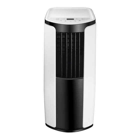
Part's Name Controller panel Guide louver Swing louver Castor Wire-fixing hook Plug of power cord Gastor Air inlet Joint A Heat discharge pipe Joint B+C Remote controller hook 11 10 AUTO HEALTH X-FAN HUMIDITY FILTER TURBO HOUR ON/OFF ON/OFF MODE X-FAN TEMP TIMER... -
Page 8: Introduction For Control Panel
Introduction for Control Panel Name of control panel Dual-8 nixie tube + / - button Cool mode indicator Health mode indicator(Optional) Dry mode indicator Fan mode indicator Heat mode indicator Cool&Heat Unit only Fan speed indicator Mode button Sleep button Timer button Fan button ON/OFF button... - Page 9 Operation Introduction for Control Panel Mode button Press this button and the mode will circulate according to below sequence: Cool→Dry→Fan→Heat Cool&Heat Unit only Cool: Under this mode, cooling mode indicator is bright. Dual-8 nixie tube displays set temperature. Temperature setting range is 16 °C~30°C. Dry: Under this mode, drying mode indicator is bright.
-
Page 10: Use Of Air Conditioner
Use of air conditioner To change air flow direction 1. Up/down air flow direction • Hold the horizental louvers as shown in the diagram and adjust the air flow direnction. • Do not adjust the horizontal louvers to the lowest or the highest position in the COOL or DRY mode with the fan speed set to Low for an extended period of time, Condensation may form on the louvers. -
Page 11: Using The Remote Control
Using the remote control This is a general purpose remote controller, it could be used for the air conditioners with multifunction; For some function, which the model doesn't have, if press the corresponding button on the remote controller that the unit will keep the original running status. -
Page 12: Buttons On Remote Controller
Buttons on remote controller ON/OFF button AUTO MODE button HEALTH X-FAN HUMIDITY +/- button FILTER TURBO FAN button HOUR ON/OFF button(Not applicable for this unit) button(Not applicable for this unit) ON/OFF HEALTH SAVE button(Optional) MODE X-FAN button (Note: X-FAN is same with BLOW) TEMP button TIMER button TURBO button... -
Page 13: Introduction For Buttons On Remote Controller
Introduction for buttons on remote controller Note: ● After putting through power, air conditioner will give out a sound and operation indicator " " is ON (red indicator). You can operate the air conditioner through the remote controller. ● At ON status, after each pressing button on remote controller, the signal icon " "... - Page 14 Introduction for buttons on remote controller Note: For preventing cold wind, after starting up heating mode, indoor fan will blow fan after delaying 1-5minutes (Details time is decided by indoor ambient temperature) Temperature setting range on remote controller: 16 ℃ -30 ℃ . Fan speed setting range: auto, low speed, medium speed and high speed.
- Page 15 Introduction for buttons on remote controller SAVE function: Under cool mode, press SAVE button and the unit will operate under SAVE mode. Dual-8nixie tube on remote controller displays "SE". Air conditioner will operate at auto speed. Set temperature can’t be adjusted. Press SAVE button again to exit SAVE mode.
-
Page 16: Function Introduction For Combination Buttons
Introduction for buttons on remote controller hour. When holding "+" or "-" button, for 2 seconds, the time will change quickly until to Cancel TIMER OFF: Press "TIMER" button again under TIMER OFF status. ● At OFF status, press this button once can set TIMER ON. Please refer to TIMER off for detailed operation. -
Page 17: Operation Guide
Operation guide 1. After putting through the power, press " " button on remote controller to ON/OFF turn on the air conditioner. 2. Press " " button to select your required mode: AUTO, COOL, DRY, FAN, MODE HEAT. Press "+" or "-" button to set your required temperature. (Temperature can not be adjusted under auto mode). -
Page 18: Clean And Maintenance
Clean and Maintenance WARNING: ● Before cleaning the air conditioner, please turn off the unit and disconnect power. Otherwise, it may cause electric shock. ● Do not wash air conditioner with water. Otherwise, it may cause electric shock. ● Do not use volatile liquid (such as thinner or gas) to clean the air conditioner. Otherwise, it may damage the appearance of air conditioner. - Page 19 Clean and Maintenance NOTICE dust in the operation environment, you can clean more frequency. dryer Clean heat discharge pipe Remove the heat discharge pipe from air conditioner, clean and dry it , and then reinstall it. (For the method of installation and removal , please refer to the instruction for "Installation and disassembly of heat discharge pipe").
-
Page 20: Malfunction Analysis
Malfunction analysis Please check below items before asking for maintenance. If the malfunction still Phenomenon Troubleshooting Solution ● Power failure? ● Wait after power recovery. ● Is plug loose? ● Reinsert the plug. ● Whether the air switch is trip- ●... - Page 21 Malfunction analysis Phenomenon Troubleshooting Solution ● Whether air outlet or air inlet is ● Eliminate the obstacles. blocked? ● Under heating mode, whether ● The unit will stop blowing indoor temperature ireaches fan after reaching set set temperature? temperature. ● In order to prevent cold air, No air flow ●...
- Page 22 Malfunction analysis Malfunction code Disconnect power, and then turn on the unit Overcurrent protection. again after 10 minutes. If "E5" still exits, please contact professional person to maintain the unit. Pour out the water inside chassis. If "H8" still exits, please contact professional Chassis is full of water.
-
Page 23: Installation Precaution
Installation Precaution WARNING: ● Observe all governing codes and ordinances. ● Do not use damaged or non-standard power cord. ● Be caution during installation and maintenance. Prohibit incorrect operation to prevent electric shock, casualty and other accidents. Selection of installation location Basic requirement Installing the unit in the following places may cause malfunction. -
Page 24: Preparation Before Installation
Preparation before Installation NOTICE: Check if the accessories are available before installation. Accessory list Joint A Joint B Joint C Heat discharge pipe Screw Pipe clip Rubber plug Pipe hoop Wire hook AUTO HEALTH X-FAN HUMIDITY FILTER TURBO HOUR ON/OFF ON/OFF MODE X-FAN... -
Page 25: Install Wire Hook
Install Wire Hook ● Assemble the wire hook at the back of the unit with screws (the direction of wire direction of wire hook is upward wire hook screw direction of wire hook is downward ● Wind the power cord around the wire hook. -
Page 26: Removing Collected Water
Removing Collected Water There are 2 ways to remove collected water: Use the continuous drainage option from the lower hole. NOTICE: When using the continuous drainage option from the bottom hole, install drainage pipe as follow before using, otherwise poor drainage will affect normal operation of the unit. - Page 27 Removing Collected Water ■ Drainage way as follows. In Cool, Dry or Heat mode operating, the condensed water will be drained to the chassis. 2. When the chassis is full with water, the buzzer will give out 8 sounds and "H8" is displayed to remind user to discharge water: ●...
- Page 28 Removing Collected Water Use the continuous drainage option from the middle hole NOTICE: Water can be automatically emptied into a floor drain by attaching 14mm inner diameter hose (not included). 1. Remove the continuous drain cap 1 by turning it counter clockwise then remove the rubber stopper 2 from the spout.
-
Page 29: Installation In A Double-Hung Sash Window(Optional)
Installation in a double-hung sash window(Optional) 1. Connect the rain guards to the insect guard net. Insert all three projections on each rain guard into the holes in the insect guard net. Side “A” will now be at the top, as indicated in the diagram. Hole Insect guard net Rain guard... - Page 30 Installation in a double-hung sash window(Optional) The window panel cannot be installed in windows less than 20.5" (520mm) wide, as you will be unable to shut the exhaust cover. (1) Open the window sash and place the window panel on the window sill. (2) Secure the window panel to the window stool with screws.
- Page 31 Installation in a double-hung sash window(Optional) 5. Close the window sash securely against the Window panel. 6. Stuff the sponge B between the glass and the window to prevent air and insects from getting into the room. 7. Attach the bracket with a screw.(Recommended) Bracket Please lay a tabular material underneath the window panel in case you could not attach the rain guard or the window adapter properly due to the deep...
-
Page 32: Installation In A Sliding Sash Window(Optional)
Installation in a sliding sash window(Optional) 1. Connect the rain guards to the insect guard net. Insert all three projections on each rain guard into the holes in the insect guard net. Side “A” will now be at the top, as indicated in the diagram. "A"... - Page 33 Installation in a sliding sash window(Optional) The window panel cannot be installed in windows less than 20.5" (520mm) high, as you will be unable to shut the exhaust cover. (1) Open the window sash and place the window panel on the window frame. (2) Secure the window panel to the window frame with screws.
- Page 34 Installation in a sliding sash window(Optional) 5. Close the window sash securely against the Window panel. 6. Stuff the sponge B between the glass and the window to prevent air and insects from getting into the room. 7. Attach the bracket with a screw.(Recommended) Bracket Please lay a tabular material underneath the window panel in case you could not attach the rain guard or the window adapter properly due to the deep...
-
Page 35: Installation And Disassembly Of Heat Discharge Pipe
Installation and Disassembly of Heat Discharge Pipe Install heat discharge pipe 1. Rotate joint A and joint B clockwise into the two ends of heat discharge pipe. clockwise clockwise joint A heat discharge pipe joint B+C 2. Insert joint A of heat clasp the side with "TOP"... - Page 36 Installation and Disassembly of Heat Discharge Pipe Note of Installingheat discharge pipe correct correct correct wrong ● The length of the heat discharge pipe is less than 1m. It is recommended to use it with shortest length. When installing,heat discharge pipe should be as flat as possible. Don’t prolong the pipe or connect it with other heat discharge pipe.
- Page 37 Installation and Disassembly of Heat Discharge Pipe should not be over 130cm from floor. would easily cause malfunction.) Disassemble heat discharge pipe 1. Remove joint A: 2. Remove joint B+C from Press the clasp and lift joint A upwards to outdoors.
-
Page 38: Operation Test
Installation and Disassembly of Heat Discharge Pipe 3. Remove the window adapter. Pull out and remove the window adapter by pushing down two “PUSH” markings, and slide and close the exhaust cover in the window panel. (Optional) "PUSH" "PUSH" Operation Test ●... - Page 40 Please record the following product information ● Model ● Serial No. ● Name of the franchiser ● Date of purchase The continuous improvement of products , such as function is changed, without prior notice, if there are any questions, please contact customer service ,Sorry for the inconvenience please forgiveness ToolBox Customer Service Centre:...
Need help?
Do you have a question about the GPAC12D and is the answer not in the manual?
Questions and answers