Table of Contents
Advertisement
Available languages
Available languages
Quick Links
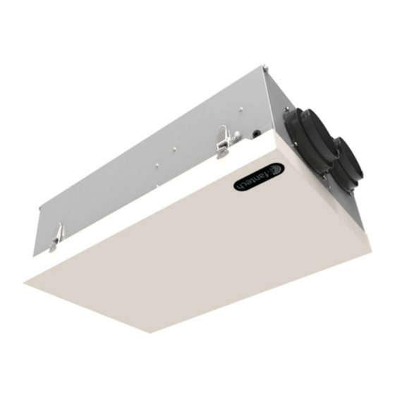
FIT ® 120H
Heat Recovery Ventilators
Your ventilation system should be installed in conformance with the appropriate provincial requirements or, in the absence of
such requirements, with the current edition of the National Building Code, and / or ASHRAE's "Good Engineering Practices".
United States
10048 Industrial Blvd., Lenexa, KS, 66215
Tel.: 800.747.1762 • Fax: 800.487.9915
Canada
50 Kanalflakt Way, Bouctouche, NB, E4S 3M5
Tel.: 800.565.3548 • Fax: 877.747.8116
Fantech reserves the right to modify, at any time and without notice, any or all of its products' features, designs,
components and specifications to maintain their technological leadership position.
Please visit our website www.fantech.net for more detailed technical information.
Installation Manual
Item #: 422622
Rev Date: 2018-11-30
Advertisement
Chapters
Table of Contents

Subscribe to Our Youtube Channel
Related Manuals for SystemAir fantech FIT 120H


Summary of Contents for SystemAir fantech FIT 120H
- Page 1 Item #: 422622 Rev Date: 2018-11-30 Installation Manual FIT ® 120H Heat Recovery Ventilators Your ventilation system should be installed in conformance with the appropriate provincial requirements or, in the absence of such requirements, with the current edition of the National Building Code, and / or ASHRAE’s “Good Engineering Practices”. United States 10048 Industrial Blvd., Lenexa, KS, 66215 Tel.: 800.747.1762 •...
- Page 2 Note Warning/ Information Technical Practical tip Important information note PLEASE READ AND SAVE THESE INSTRUCTIONS For residential use only Before installation careful consideration must be given to how this system will operate if connected to any other piece of mechanical equipment, i.e. a forced air furnace or air handler operating at a higher static pressure.
-
Page 3: Table Of Contents
TABLE OF CONTENTS DETERMINING YOUR AIRFLOW REQUIREMENT ........... . . 4 INSTALLATION EXAMPLES Fully dedicated system . -
Page 4: Determining Your Airflow Requirement
DETERMINING YOUR AIRFLOW REQUIREMENT Room Count Method Room classification Number of rooms CFM (L/s) CFM Required Master bedroom x 10 L/s (20 CFM) if yes add 10 L/s (20 CFM) Basement yes or no if no = 0 Bedrooms x 5 L/s (10 CFM) Living room x 5 L/s (10 CFM) Others... -
Page 5: Installation Examples
Installation examples Suggested installation for: • Hydronic baseboard • Infloor heating • Electric baseboard • Mini split heat pump FULLY DEDICATED SYSTEM Benefits: Provides the best BEST FOR NEW CONSTRUCTION fresh air distribution in the Stale air is drawn from key areas of home (bathroom, kitchen, laundry) house;... -
Page 6: Partially Dedicated System
Installation examples (Cont'd) Suggested installation for: • Central furnace (air DIRECT CONNECTION of the FRESH air to living area to the RETURN PLENUM handling unit or central of the AIR HANDLER (Stale air drawn from key areas of home) air conditioners) •... -
Page 7: Simplified Installation
Installation examples (Cont'd) Suggested installation for: DIRECT CONNECTION of both the HRV SUPPLY AIR STREAM and EXHAUST AIR STREAM • When bathroom and kitchen to the FURNACE COLD AIR RETURN already have local exhaust system SIMPLIFIED INSTALLATION (GOOD) (RETURN/RETURN METHOD) - OPTION 1 •... - Page 8 Installation examples (Cont'd) Suggested installation for: DIRECT CONNECTION of the HRV SUPPLY AIR STREAM to the SUPPLY AIR SIDE on the • When bathroom and FURNACE & EXHAUST AIR STREAM to the FURNACE COLD AIR RETURN kitchen already have local exhaust system SIMPLIFIED INSTALLATION (GOOD) - OPTION 2 •...
-
Page 9: Exterior Ducting Installation
EXTERIOR DUCTING INSTALLATION WEATHERHOOD LOCATION OUTSIDE CORNER INSIDE CORNER • Decide where your intake and exhaust hoods will be located. 36" (1m) 36” (1m) min. min. Locating the Intake Weatherhood • Should be located upstream (if there are prevailing winds) from the 6' (2m) exhaust outlet. -
Page 10: Interior Ducting Installation
Interior ducting installation • To maximize airflow through the ductwork system, all ducts should be kept short and have as few bends or elbows as possible. • 45º elbows are preferable to 90º. • Use “Y“ ducts instead of “T” ducts whenever possible. •... -
Page 11: Hrv Installation
HRV installation LOCATION The HRV must be located in a conditioned space where it will be possible to conveniently service the unit. Typically the HRV would be located in the mechanical room or an area close to the outside wall where the weatherhoods will be mounted. -
Page 12: Mounting
Mounting MOUNTING BRACKET 1 Insert the middle screw with washer in the mounting bracket through 2 Insert screws with washers on both side of the bracket to secure. the rubber insulator. Ensure the bracket is straight. 3 Remove the screw and the washer on the unit to install bracket 4 Install bracket and replace screw and washer. - Page 13 6 Secure both side of the unit using the same method as step 1. Mounting CHAIN - OPTION 1 Place your fastening hooks on the strapping board, the floor joists or underneath the concrete floor. 2 Attach a hanging chain to each screw paired with a washer (provided) in the top 4 corners of the unit and tighten.
-
Page 14: Drain Line Installation
Drain line installation Through normal operation and during its defrost mode, the HRV may produce some condensation. This water should flow into a nearby drain, or be taken away by a condensate pump. The HRV and all condensate lines must be installed in a space where the temperature is maintained above the freezing point. A “P”... -
Page 15: Airflow Adjustment & Balancing
Airflow adjustment & balancing BALANCING THE AIRFLOWS IS CRUCIAL TO ENSURE OPTIMAL OPERATION OF THE UNIT. IF THE AIRFLOW IS NOT PROPERLY BALANCED, THE FOLLOWING ISSUES MAY OCCUR: • SIGNIFICANT POSITIVE OR NEGATIVE PRESSURE INSIDE THE HOUSE • UNIT’S EFFICIENCY MAY BE NEGATIVELY AFFECTED •... -
Page 16: Balancing Steps
Airflow balancing (Cont'd) Adjusting airflows A damper is integrated into the Fresh Air to Building collar. This damper replaces the installation of a separate damper into the Fresh Air to Building ducting line. The damper-collar is pre-set in the fully opened position. If the procedure requires a reduction in airflow to the fresh air duct, simply turn the adjustable arm located on the side of the collar counter clockwise until desired airflow is obtained. -
Page 17: Low Voltage Control Systems
Low Voltage Control Systems * Please see instruction manuals for individual controls for proper wiring and set up of control systems. CENTRAL CONTROLS These control options can only be used individually Ensure that unit is not CONTROLS FEATURES CONNECT TO plugged when connecting ECO-TOUCH ®... -
Page 18: Wiring Diagram
Wiring diagram HIGH... - Page 19 Wiring diagram (CONT'D) WIRING DIAGRAM TO Standard Accessory Control Contact Standard Furnace Interlock Wiring FURNACE THERMOSTAT TERMINALS FOUR WIRE TWO WIRE heating only FOR A FURNACE CONNECTION TO A COOLING SYSTEM: On some newer furnaces and older FURNACE thermostats, energizing the R and 24-VOLT TERMINAL BLOCK G terminal at the furnace has the...
-
Page 20: Troubleshooting
Troubleshooting Problem Causes Solutions Air is too dry Dehumidistat control is set too low Increase the desired level of humidity. Change ventilation mode from continuous mode to standby. HRV out of balance Have contractor balance HRV airflows Air is too humid Dehumidistat control is set too high Reduce the desired level of humidity. -
Page 21: Hrv Maintenance Chart
HRV maintenance chart Limited Warranty • The Heat recovery aluminum core has a Limited Lifetime Warranty. Maintenance Required Recommended Frequency Date Maintenance Performed Check and Clean Filters Every 3 months or if • The warranty is limited to 5 years on parts and 7 years on fans from the dirty date of purchase, including parts... - Page 22 Notes...
- Page 23 No. d'article #: 422622 Date de révision: 2018-11-30 Manuel d'installation FIT ® 120H Ventilateur récupérateur de chaleur Votre système de ventilation doit être installé conformément aux exigences de la province où vous habitez ou, à défaut de telles exigences, conformément à l’édition actuelle du Code national du bâtiment du Canada ou aux « méthodes d’ingénierie appropriées »...
- Page 24 Note Avertissement/ Information Information Conseil Note importante technique pratique VEUILLEZ LIRE ET CONSERVER CES INSTRUCTIONS À fin d’installation résidentielle seulement Avant de procéder à l’installation, examinez avec soin la façon dont le système fonctionnera s’il est relié à tout autre appareil mécanique, notamment une fournaise à air pulsé ou un appareil de traitement d’air dont la pression statique est plus élevée.
- Page 25 TABLE DES MATIÈRES DÉTERMINER VOS BESOINS DE VENTILATION ........... . . 26 EXEMPLES D'INSTALLATION Système entièrement spécialisé...
-
Page 26: Déterminer Vos Besoins De Ventilation
DÉTERMINER VOS BESOINS DE VENTILATION Méthode compte de pièces Pi 3 /min (L/s) Liste des pièces Nombre de pièces PCM Required x 10 L/s (20 pi 3 /min) Chambre principale 3 /min Si oui, ajoutez 10 L/s (20 pi Sous-sol oui ou no Sinon = 0 x 5 L/s (10 pi 3 /min) -
Page 27: Exemples D'installation
Exemples d'installation Installation suggéré pour: Exemple seulement - La configuration des conduits peut être différente selon le modèle. • Plinthe à eau chaude • Chauffage de planché • Plinthe électriques • Thermopompe mural bibloc Avantages: Fourni la meilleure SYSTÈME ENTIÈREMENT SPÉCIALISÉ répartition de l’air frais dans (NOUVELLE CONSTRUCTION) la maison;... -
Page 28: Système Partiellement Spécialisé
Exemples d'installation (Suite) Installation suggérée pour: RACCORDEMENT DIRECT du FLUX D’AIR D’APPROVISIONNEMENT à la BOUCHE DE REPRISE • Fournaise centrale (unité D’AIR DE LA FOURNAISE de traitement d’air, air (L’air vicié est aspiré à partir des endroits clés de la maison.) climatisé... -
Page 29: Installation Simplifiée
Exemples d'installation (Suite) Installation suggérée pour: RACCORDEMENT DIRECT du FLUX D’AIR D’APPROVISIONNEMENT et du FLUX D’AIR ÉVACUÉ • Lorsque la salle de bain DU VRC à la BOUCHE D’AIR DE LA FOURNAISE et la cuisine ont déjà un système d’échappement INSTALLATION SIMPLIFIÉE (BONNE) - OPTION 1 •... - Page 30 Exemple d'installation (Suite) Installation suggérée pour: RACCORDEMENT DIRECT du FLUX D’AIR D’APPROVISIONNEMENT du VRC à la BOUCHE DE • Lorsque la salle de bain REPRISE D’AIR DE LA FOURNAISE et la cuisine ont déjà un système d’échappement INSTALLATION SIMPLIFIÉE (BONNE) •...
-
Page 31: Installation Des Conduits Extérieurs
INSTALLATION DES CONDUITS EXTÉRIEURS EMPLACEMENT DES HOTTES Coin extéreur Coin intérieur OUTSIDE CORNER INSIDE CORNER • Décidez de l’emplacement des hottes d’aspiration et d’évacuation. 36po (1m) 36po (1m) 36" (1m) 36” (1m) min. min. Emplacement de la hotte d’aspiration • Doit être située en amont de la sortie d’évacuation (en présence de vents 3pi (900 mm) dominants). -
Page 32: Installation Des Conduits Intérieurs
Installation des conduits intérieurs • Pour maximiser le débit d’air dans le réseau de conduits, assurez-vous que tous les conduits sont le plus court et le plus droit possible. • Il est préférable d’utiliser des coudes de 45 degrés plutôt que des coudes de 90 degrés. •... -
Page 33: Installation Du Vrc
Installation du VRC EMPLACEMENT Le VRC doit être situé dans un endroit chauffé où il sera possible d’en effectuer l'entretient convenablement. Généralement, le VRC doit être situé dans la chambre des appareils mécaniques ou à proximité. S’il n’y a pas de sous-sol ou si le sous-sol ne convient pas, il est possible d’installer l’appareil dans la lingerie ou dans la buanderie. -
Page 34: Montage
MONTAGE SUPPORT 1 Insérez la vis et la rondelle du milieu dans le support de montage à 2 Insérez les vis et rondelles des deux côtés du support pour fixer. travers l'isolant en caoutchouc. Assurez le support est droit. 3 Enlevez la vis et la rondelle de l'appareil pour placer le support. 4 Installez le support et remettre la vis et la rondelle. - Page 35 6 Fixer les deux côtés de l'appareil en utilisant le même procédé que l'étape 1 MONTAGE CHAÎNES - OPTION 1 Installez les crochets de fixation sur la fourrure, les solives de plancher ou sous le plancher de béton 2 Suspendez la chaîne à chaque vis appariée avec une rondelle (fournis) situés aux quatre coins supérieurs du VRC et serrez.
-
Page 36: Installation Du Tuyau D'écoulement
Installation du tuyau d'écoulement En mode normal ainsi qu’au cours du cycle de dégivrage, le VRC peut produire de la condensation. L’eau de condensation doit s'écouler vers le drain avoisinant ou être aspirée par une pompe à condensat. Le VRC et toutes les canalisations de condensats doivent être installés dans un endroit où la température ambiante est maintenue au-dessus du point de congélation. -
Page 37: Équilibrage Du Débit D'air
Équilibrage du débit d'air SI LES FLUX D’AIR DE L’APPAREIL NE SONT PAS CORRECTEMENT ÉQUILIBRÉS… • L’EFFICACITÉ DE L’APPAREIL PEUT ÊTRE RÉDUITE. • DES DOMMAGES AU NOYAU DE RÉTABLISSEMENT DE LA CHALEUR PEUVENT SURVENIR. • UN REFOULEMENT DE L’AIR DANS VOS APPAREILS DE CHAUFFAGE À COMBUSTION •... -
Page 38: Étapes De Balancement
Équilibrage du débit d'air (suite) Ajustement des débits d'air Un registre est intégré dans le collet d'air frais distribué à l'intérieur. Ce registre remplace l'installation d'un registre dans les conduits de distribution d'air frais à l'intérieur. Par défaut, le registre du collet est complètement ouvert. Si la procédure nécessite une réduction du flot d'air dans le conduit d'air frais, simplement tournez, dans le sens antihoraire, la molette de positionnement située sur le côté... -
Page 39: Systèmes De Contrôle À Basse Tension
SYSTÈME DE CONTRÔLE À BASSE TENSION * Veuillez voir les instructions individuelles des contrôles pour le câblage et la mise en pièce appropriée. CONTRÔLES CENTRALS Ces options de contrôle peuvent seulement être utilisé individuellement Assurez-vous que CONTRÔLE CARACTÉRISTIQUES CONNEXION À l'appareil n'est pas ECO-TOUCH ®... -
Page 40: Shémas Électriques
Schémas électroniques HIGH... - Page 41 Schémas électroniques (SUITE) CONNEXION ÉLECTRIQUE Câblage standard de synchronisation avec une fournaise Standard Furnace Interlock Wiring À UNE FOURNAISE BORNES DU THERMOSTAT TERMINALS TERMINALS FOUR QUATRE FILS WIRE DEUX FILS TWO WIRE chauffage seulement heating only DANS LE CAS D'UNE FOURNAISE RACCORDÉE À...
-
Page 42: Dépannage
Dépannage Problème Causes Solutions L’air est trop sec – Le déshumidistat est réglé trop bas – Augmentez le niveau voulu d’humidité. Faites passer le mode de ventilation de « continu » à « attente ». – Le VRC est déséquilibré –... -
Page 43: Tableau D'entretien Du Vrc
Tableau d'entretien du VRC La meilleure garantie limitée sur le marché • La meilleure garantie limitée sur le Entretien requis Fréquence recommandée Date de l'entretien marché. Vérifiez et nettoyez les à chaque 3 mois, ou s'ils • Le noyau récupérateur de chaleur filtres sont sales en aluminium bénéfice d'une... -
Page 44: Parts List
Parts list • Liste des composantes FIT120H BOM # Description (75064) R2E 190 Radical, Rep. Kit 414382 Electrostatic Filters Kit 422580 Heat Recovery Cell 12” x 12” x 7.7” 424025 * If the first set of digits (can be between 7 and Capacitors 8uF 410012 10 digits long) of your serial number is #2476161... - Page 45 Notes...
- Page 46 Notes...
- Page 47 Notes...
- Page 48 Fantech reserves the right to make technical changes. Fantech se réserve le droit de faire des changements tech- For updated documentation please refer to www.fantech.net niques. Pour de la documentation à jour, s'il vous plaît se référer au www.fantech.net Fantech®...
Need help?
Do you have a question about the fantech FIT 120H and is the answer not in the manual?
Questions and answers