Sign In
Upload
Manuals
Brands
ST Manuals
Motherboard
EVALSPEAr320PLC
ST EVALSPEAr320PLC Manuals
Manuals and User Guides for ST EVALSPEAr320PLC. We have
1
ST EVALSPEAr320PLC manual available for free PDF download: User Manual
ST EVALSPEAr320PLC User Manual (50 pages)
Brand:
ST
| Category:
Motherboard
| Size: 0 MB
Table of Contents
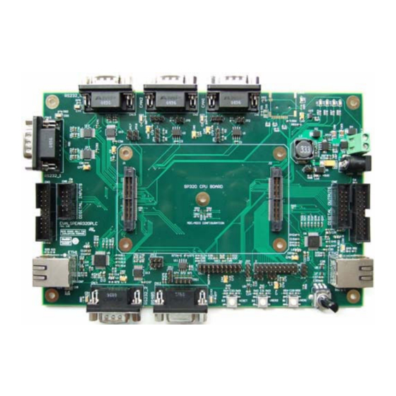
Figure 1. Spear320 MII Mode Application Board
1
Table of Contents
2
CPU Board Features
6
CPU Board Block Diagram
6
Figure 2. CPU Board Block Diagram
6
Application Board Features
7
Application Board Block Diagram
7
Figure 3. Block Diagram
7
Application Board Layout
8
Figure 4. Application Board Layout
8
Getting Started
9
Unpacking
9
Connecting
9
Bootinging
9
Configuration
10
Ethernet
10
Table 1. MII Addresses of the Ethernet Phys (U5 and U6)
10
Table 2. Default Configuration of the Ethernet Phys (U5 and U6)
10
Table 3. SMI Interface Configuration
10
Digital Input / Digital Output Connectors
11
Figure 5. EVALSPEAR320PLC Board with Digital Input and Digital Output Cards
11
Controller-Area Network Bus
12
Figure 6. 8/16 Input Channel Current Limiter Based on SCLT3-8, STEVAL-IFP007V1
12
Table 4. CAN0 Transceiver Settings
12
RS-232 and RS-485 Transceivers
13
Table 5. CAN1 Transceiver Settings
13
Table 6. UART2 RS-232/RS-485 Configuration
13
Power Supply
14
Table 7. UART0/RS-232 Transceiver Signals from the CPU Board
14
Temperature Sensor
15
Potentiometer
15
General-Purpose ADC Connector
15
Table 8. U16 DC/DC Converter Jumpers
15
General-Purpose Buttons (B1 and B2)
16
Leds
16
Table 9. ADC Conversion Settings
16
Table 10. General-Purpose LED Configuration
16
Reset Button
17
Microsd Card
17
Connectors
18
CAN DB9 Plug Connectors (CN1 and CN2)
18
Digital Input Serial Connector (CN3)
18
Figure 7. CAN DB9 Plug Connectors Pinout
18
Figure 8. Digital Input Serial Connector Pinout
18
Table 11. CAN DB9 Plug Connectors Description
18
Table 12. Digital Input Serial Connector Description
18
Digital Output Serial Connector (CN4)
19
Digital Input Parallel Connector (CN5)
19
Figure 9. Digital Output Serial Connector Pinout
19
Figure 10. Digital Input Parallel Connector (CN5) Pinout
19
Table 13. Digital Output Serial Connector Description
19
Table 14. Digital Input Parallel Connector (CN5) Description
19
Digital Output Parallel Connector (CN6)
20
Ethernet RJ-45 Connectors (CN7 and CN8)
20
Figure 11. Digital Output Parallel Connector (CN6) Pinout
20
Figure 12. Ethernet RJ-45 Connectors (CN7 and CN8) - Front View
20
Table 15. Digital Output Parallel Connector (CN6) Description
20
Table 16. Ethernet RJ-45 Connectors (CN7 and CN8) Description
20
General-Purpose ADC Connector (CN9)
21
General-Purpose GPIO and I2C Connector (CN10)
21
Figure 13. General-Purpose ADC Connector (CN9) Pinout
21
Figure 14. General-Purpose GPIO and I2C Connector (CN10) Pinout
21
Table 17. General-Purpose ADC Connector (CN9) Description
21
Table 18. General-Purpose GPIO and I2C Connector (CN10) Pinout Description
21
RS-485 DB9 Socket and Header Connector (CN11 and CN12)
22
RS-232/UART0 DB9 Plug Connector (CN13)
22
Figure 15. RS-485 DB9 Socket Connector CN11 Pinout
22
Figure 16. RS-485 Header Connector CN12 Pinout
22
Figure 17. RS-232/UART0 DB9 Plug Connector (CN13) Pinout
22
Table 19. RS-485 DB9 Socket Connector CN11 Description
22
Table 20. RS-485 Header Connector CN12 Description
22
RS-232/UART2 DB9 Plug Connector (CN14)
23
RS-232/UART1 DB9 Plug Connector (CN15)
23
Figure 18. RS-232/UART2 DB9 Plug Connector (CN14) Pinout
23
Figure 19. RS-232/UART1 DB9 Plug Connector (CN15) Pinout
23
Table 21. RS-232/UART0 DB9 Plug Connector (CN13) Description
23
Table 22. RS-232/UART2 DB9 Plug Connector (CN14) Description
23
Microsd Card Connector (CN16)
24
Figure 20. Microsd Card Connector (CN16) Pinout
24
Table 23. RS-232/UART1 DB9 Plug Connector (CN15) Description
24
Table 24. Microsd Card Connector (CN16) Description
24
Power Supply Connectors (CN17 and CN18)
25
Spear320 CPU Board Connectors (J1 and J2)
25
Figure 21. Power Supply Connector CN18 Diagram
25
Figure 22. Power Supply Connector CN17 Diagram
25
Figure 23. 86-Pin Connectors (J1 and J2) Pinout
25
Table 25. Power Supply Connector CN18 Description
25
Table 26. Power Supply Connector CN17 Description
25
Table 27. 86-Pin Connector (J1) Description
26
Table 28. 86-Pin Connector (J2) Description
26
Appendix A CPU Board Hardware Description
28
CPU Board Layout
28
Figure 24. CPU Board Layout (Top View)
28
Figure 25. CPU Board Layout (Bottom View)
28
Block Descriptions
29
Dynamic Memory Subsystem
29
Static Memory Subsystem
29
USB 2.0 Subsystem
29
Debug Interface
29
Serial Interface
30
Real Time Clock (Battery Powered)
30
General Power Supply
30
Figure 26. Serial Cable Setting
30
Table 29. Switch SW1 Bits [2:1]
30
CPU Board Switch and Jumper Settings
31
Switch 1 Settings
31
Table 30. Switch 1 (Soc Functional Configuration)
31
Table 31. Switch 1 (Debug Configuration)
31
Table 32. Switch 1 (Functional Configuration)
31
Switch 2 Settings
32
Table 33. Switch 2 Settings
32
Jumpers & Connectors
33
CPU Board Expansion Connectors
34
Table 34. CPU Board Extension Connector J12
34
Table 35. CPU Board Extension Connector J13
35
CPU Board Bill of Materials
36
Table 36. List of Components
37
Appendix B Application Board Bill of Materials
41
Table 37. List of Components
41
Appendix C License Agreements
44
Revision History
49
Table 38. Document Revision History
49
Advertisement
Advertisement
Related Products
ST EVALSPEAr300
ST EVALSPEAr320CPU
ST EVALSP320SPLC
ST EVALSP1340CPU
ST EVALSP820-XS
ST EVALSP320SCPU
ST EVALSP1310CPU
ST EVALSTPM34
ST EVALSTPM32
ST EVALST-3PHISOSD
ST Categories
Motherboard
Computer Hardware
Microcontrollers
Control Unit
Controller
More ST Manuals
Login
Sign In
OR
Sign in with Facebook
Sign in with Google
Upload manual
Upload from disk
Upload from URL