
Subscribe to Our Youtube Channel
Related Manuals for multicomp pro MP710083


Summary of Contents for multicomp pro MP710083
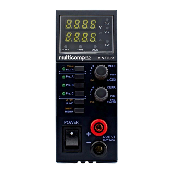
- Page 1 REMOTE PROGRAMMABLE POWER SUPPLY AND DC WAVE FORM GENERATOR WITH ETHERNET NETWORK CONNECTIVITY Model: MP710083...
-
Page 2: Table Of Contents
Table of Contents PRECAUTONS 1.1 WARNING 1.2 CAUTION 1.3 Operation environmental condition ACCESSORIES INTRODUCTION SPECIFICATIONS INDICATORS and CONTROLS 5.1 Display and Indications 5.2 Control Buttons and Knobs 5.3 Back Panel OPERATION PROCEDURES 6.1 Adjusting Output Voltage and Current 6.2 Upper Voltage and Current Limit adjustment 6.3 Select and adjust 3 preset value of Voltage and Current 6.4 Output ON / OFF (Include power up ON / OFF setting) 6.5 Lock / Unlock of front panel... -
Page 3: Precautons
1. PRECAUTIONS Keep this manual in a safe place for quick reference at all times. This manual contains important safety and operation instructions for correct use of the power supply. Read through the manual and pay special attention to the markings and labels of this unit and equipment to be connected. -
Page 4: Accessories
2. ACCESSORIES USB cable 3. INTRODUCTION This Remote Programmable Constant Power SMPS with DC wave forms & Optional Ethernet Card. This multi- function constant power laboratory grade power supply is capable of generating various DC wave forms. A micro-processor is used for such DC waveform. There are 10 voltage generators which can either be panel programmed or by PC via remote control port. -
Page 5: Specifications
4. SPECIFICATIONS MP780083 Models Input Voltage Range 100 – 240VAC ≤150mA No Load Input Current at 230VAC Full Load Input Current at 230VAC ≤500mA AC input Frequency 50 – 60 Hz~ Efficiency ≥78% Power Factor ≥0.9 Constant Voltage and Current Range Selection: Auto range with maximum output power 80W (V x A ≤80W) 0.5-36V / 0-5A Constant Voltage Characteristics:... -
Page 6: Indicators And Controls
5. INDICATORS AND CONTROLS 5.1 Display and Indications Constant Voltage Mode Indicate the Power Supply is working in Constant Voltage mode. The output voltage of power supply is remains constant at the set voltage in this mode. The power supply will be working in this mode while the loading current is least than the set current. -
Page 7: Control Buttons And Knobs
Output ON/OFF or Ramp UP/Ramp Down program running This LED has two indications. a. When it is solid ON, it indicate output ON/OFF status. b. When it is Flashing, it indicate ramp up/ramp down program is running (Refer to Ramp Up / Ramp Down generator section) Preset A Indicate Preset A is selected, the output voltage and current will set preset A value. -
Page 8: Back Panel
5.3 Back Panel ➀ USB communication port ➁ Remote sensing terminals ➂ DC output terminal which has same power rating as the front output ④ Master/Slave connection ➄ AC INPUT SOCKET ➅ ETHERNET port (Not Included) 6. OPERATION PROCEDURES 6.1 Adjusting Output Voltage and Current Adjust Output Voltage: Rotate Voltage Knob clockwise to INCREASE output voltage Rotate Voltage Knob anti-clockwise to REDUCE output voltage... -
Page 9: Upper Voltage And Current Limit Adjustment
6.2 Upper Voltage and Current Limit adjustment Upper Voltage Limit (UVL) The Upper Voltage Limit is feature to let user to set maximum value for voltage adjustment. This feature can help to prevent accidentally adjust to very high output voltage to cause damage on object under testing. During increasing output voltage and hit the UVL, the display will show you alert as follow;... -
Page 10: Select And Adjust 3 Preset Value Of Voltage And Current
- Rotate Current Knob to adjust the value. - Press to confirm setting. If the new UCL value is lower than set current, it will show UCL Error alert. Just reduce the set current to lower than the UCL value. Then the UCL Error will OFF. 6.3 Select and adjust 3 preset value of Voltage and Current This power supply has 3 preset program of Voltage and Current value for quick recall to use. -
Page 11: Ramp Up/ Ramp Down Generator
6.7 Ramp Up/ Ramp Down generator The MP710083 has function to generate waveform with ramp up and ramp down. It allow to set 10 steps for wave. Steps to setup ramp up/ramp down wave; Step 1 - Press and hold to enter menu Step 2 - Rotate Volt. - Page 12 Examples, Example 1 – Triangular Waveform. Setting value Set Item Value Explaination Set 2 steps to run. Step 1 and Step 2 Run 3 cycle only Set Step 1 voltage to 2.5V Set Step 1 run time to 3s (Ramp UP from step 1 voltage to step 2 voltage in 3s) Set Step 2 voltage to 12V Set Step 2 run time to 3s (Ramp DOWN from step 2 voltage to step 1 voltage in 3s)
- Page 13 Example 3 – Rectangular Waveform Setting value Set Item Value Explanation Set 4 steps to run. From step 1 to step 4 Run 4 cycle only Set Step 1 voltage to 2.5V Set Step 1 run time to 0s (Edge UP from step 1 voltage to step 2 voltage in 0s) Set Step 2 voltage to 12V Set Step 2 run time to 3s (Keep at 12V by 3s, since step 2 voltage = step 3 voltage)
- Page 14 Example 4 – irregular waveform Setting value Set Item Value Explanation Set 7 steps to run. From Step 1 to Step 7 Run forever Set Step 1 voltage to 2.5V Set Step 1 run time to 3s (Ramp UP from step 1 voltage to step 2 voltage in 3s) Set Step 2 voltage to 12V Set Step 2 run time to 5s (Keep at 12V by 5s, since step 2 voltage = step 3 voltage)
-
Page 15: Master/ Slave Configuration
6.8 Master/ Slave configuration The power supply can be configured for Master/ Slave connection. When systems are connected in Master/ Slave, the Slaves’ output will follow the setting of Master. The set voltage will same for Master and all Slave system. The load current will share over all units. That means 10Amp share to 5 units will make every unit carry 2Amp. -
Page 16: Factory Reset
The power will reset immediately. 6.10 Remote control interface selection The MP710083 has a USB port for use via remote control. The Ethernet Card is an optional accessory. The remote control interface can be selected in menu. Steps for Remote Control interface selection;...
Need help?
Do you have a question about the MP710083 and is the answer not in the manual?
Questions and answers