
Related Manuals for Kramer VP-774A


Summary of Contents for Kramer VP-774A
- Page 1 K R A ME R E LE CT R O N IC S L TD . USER MANUAL MODEL: VP-774AMP Presentation Switcher/Scaler P/N: 2900-300324 Rev 2...
-
Page 4: Table Of Contents
Contents Introduction Getting Started Achieving the Best Performance Safety Instructions Recycling Kramer Products Overview HDCP Compliance About HDBaseT™ Technology Using Twisted Pair Cable Defining the VP-774AMP Presentation Switcher/Scaler Installing in a Rack Connecting the VP-774AMP Wiring the RJ-45 Connectors Connecting the Balanced Stereo Audio Output... - Page 5 Technical Specifications 12.1 Default Communication Parameters 12.2 Input Resolutions 12.3 Output Resolutions The VP-774AMP RS-232 Communication Protocol 13.1 Using the Communication Protocol 13.2 Communication Protocol: Mimicking OSD 13.3 Protocol Table: Mimicking Remote and Front Panel Buttons 13.4 The Protocol 3000 Common Operation Commands Figures Figure 1: VP-774AMP Presentation Switcher/Scaler Front Panel Figure 2: VP-774AMP Presentation Switcher/Scaler Rear Panel...
- Page 6 Figure 42: The Routing & Scaling Page – Single Window Figure 43: The Routing & Scaling Page – Moving the PIP Window Figure 44: The Routing & Scaling Page – PIP Window Figure 45: The Routing & Scaling Page – Changing the Resolution Figure 46: The Routing &...
-
Page 7: Introduction
Introduction Welcome to Kramer Electronics! Since 1981, Kramer Electronics has been providing a world of unique, creative, and affordable solutions to the vast range of problems that confront video, audio, presentation, and broadcasting professionals on a daily basis. In recent years, we have redesigned and upgraded most of our... -
Page 8: Getting Started
Achieving the Best Performance To achieve the best performance: Use only good quality connection cables (we recommend Kramer high- performance, high-resolution cables) to avoid interference, deterioration in signal quality due to poor matching, and elevated noise levels (often associated with low quality cables) ... -
Page 9: Recycling Kramer Products
Kramer Electronics has made arrangements with the European Advanced Recycling Network (EARN) and will cover any costs of treatment, recycling and recovery of waste Kramer Electronics branded equipment on arrival at the EARN facility. For details of Kramer’s recycling arrangements in your particular country go to our recycling pages at http://www.kramerelectronics.com/support/recycling/. -
Page 10: Overview
Overview The Kramer VP-774AMP is a high quality presentation switcher and scaler. It accepts one of nine inputs: an SDI signal on a BNC connector, a DisplayPort (DP) signal on a DisplayPort connector, one composite video signal on an RCA connector, two computer graphics signals on 15-pin HD connectors, and four HDMI signals on HDMI connectors. - Page 11 System Range - Up to 130m (430ft) normal mode; up to 180m (590ft) ultra- mode (1080p @60Hz @24bpp) when using BC−HDKat6a cables For optimum range and performance using HDBaseT™, use Kramer's BC−HDKat6a cable. Note that the transmission range depends on the signal resolution, source and display used.
- Page 12 Selectable Power Save modes for energy efficient usage HDCP Compliant - The HDCP (High Definition Content Protection) license agreement allows copy-protected data on the HDMI input to pass only to the HDMI and HDBaseT outputs In addition, the VP-774AMP Presentation Switcher / Scaler: ...
-
Page 13: Hdcp Compliance
IR, as well as various control signals. The products described in this user manual are HDBaseT certified. Using Twisted Pair Cable Kramer engineers have developed special twisted pair cables to best match our BC−HDKat6a digital twisted pair products; (CAT 6 23 AWG cable) significantly outperforms regular CAT 5 / CAT 6 cables. -
Page 14: Figure 1: Vp-774Amp Presentation Switcher/Scaler Front Panel
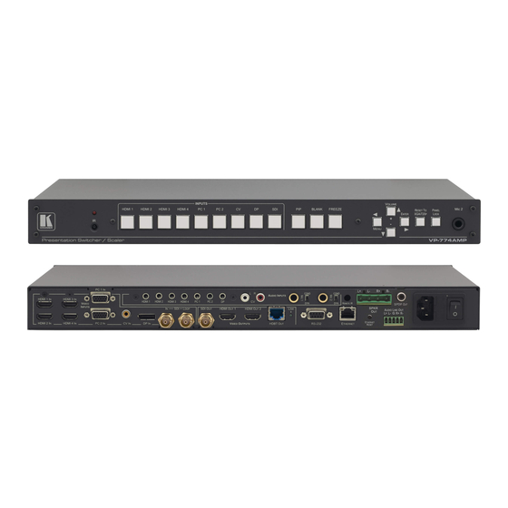
Figure 1: VP-774AMP Presentation Switcher/Scaler Front Panel Feature Function IR Receiver Accepts IR remote commands IR LED Lights red when the unit accepts IR remote commands INPUT Selector HDMI Press to select the HDMI input (from 1 to 4) Buttons Press to select the computer graphics input (from 1 to 2) Press to select the composite video input (from 1 to 2) Press to select the Display Port input... -
Page 15: Figure 2: Vp-774Amp Presentation Switcher/Scaler Rear Panel
Figure 2: VP-774AMP Presentation Switcher/Scaler Rear Panel Feature Function AUDIO IN HDMI 3.5mm Mini Jack Connect to an unbalanced audio source for audio takeover of the HDMI 1 to HDMI 4 embedded audio (see Unbalanced Section 6.3). The pinout is defined in Section 5.4 Connectors PC 3.5mm Mini Jack... - Page 16 Connect to an SDI acceptor HDMI OUT Connect to an HDMI acceptor (from 1 to 2) VIDEO OUTPUT Connect to an HDBT receiver (for example, Kramer TP-580Rxr) to pass audio and video signals as well as HDBT OUT RJ-45 Connectors serial commands LINK LED...
-
Page 17: Installing In A Rack
Installing in a Rack This section provides instructions for rack mounting the unit. VP-774AMP - Installing in a Rack... -
Page 18: Connecting The Vp-774Amp
Connecting the VP-774AMP Always switch off the power to each device before connecting it to your VP-774AMP. After connecting your VP-774AMP, connect its power and then switch on the power to each device. You do not have to connect all the inputs and outputs, connect only those that are required. - Page 19 LCD display). You can also connect the HDMI OUT 2 output (not shown in Figure 10. Connect the HDBT RJ-45 connector to a receiver (for example, the Kramer TP-580Rxr). 11. Connect the AUDIO LINE OUT Terminal Block connector to a balanced...
-
Page 20: Figure 4: Connecting The Vp-774Amp Presentation Switcher/Scaler
Figure 4: Connecting the VP-774AMP Presentation Switcher/Scaler VP-774AMP - Connecting the VP-774AMP... -
Page 21: Wiring The Rj-45 Connectors
Wiring the RJ-45 Connectors This section defines the TP pinout, using a straight pin-to-pin cable with RJ-45 connectors. Figure 5: TP PINOUT EIA /TIA 568B Wire Color Orange / White Orange Green / White Blue Blue / White Green Brown / White Brown VP-774AMP - Connecting the VP-774AMP... -
Page 22: Connecting The Balanced Stereo Audio Output
Connecting the Balanced Stereo Audio Output Figure 6: Connecting the Balanced Figure 7: Connecting an Unbalanced Stereo Stereo Audio Output Audio Acceptor to the Balanced Output Microphone Pinout This section defines the microphone 6mm jack pinout. Figure 8: Microphone Pinout Audio Input Pinout This section defines the audio input 3.5mm jack... -
Page 23: The Osd Menu
The OSD Menu The VP-774AMP OSD menu lets you set the operation parameters for the: Main Window Control PIP Window Control Entire System Control The nature of the operation setup appears in the OSD title, as shown in the example in Section 6.1:... - Page 24 The subtitle, below the title line shows the current level accessed (Scale in this example) After selecting Output (which is the second Level), it appears in the subtitle Once Master Connection is selected, the Title changes to “Entire System Control” indicating that the selection will affect the entire system.
- Page 25 Note that: A selected parameter that turns gray becomes valid immediately. You can press Enter at this point to save these parameter changes to the memory immediately (the screen will display “Saving Data” for a split second). In any case, exiting the menu saves the parameter to the memory ...
-
Page 26: The Input Menu
The Input Menu Figure 10: Input Menu Setting Function Display Mode Select the display mode (see Figure 11): Single Window – single window mode operation with one channel displayed Picture in Picture (PiP) – dual window mode operation, a smaller window superimposed over a full screen image (see Section 7.2) - Page 27 Setting Function Input Settings Set the: H Image Shift – to set the horizontal position of the image within the window Volatile parameter V Image Shift – to set the vertical position of the image within the window Volatile parameter Auto Positioning –...
-
Page 28: Figure 11: Select The Display Mode
Setting Function Image Shift Mode – to get the best image positioning possible. Set to Auto to Input Settings (continued) automatically get the best possible image positioning automatically; set to Semi-auto to store the best image possible until the video resolution of the selected input is changed (in which case the setting bounces to Auto);... -
Page 29: Figure 12: Changing The Size Of The Window
6.2.1 Window Customization Window customization lets you change the size and position of a selected window. Make sure that you have control over the window that requires customization (Main Window Control or PiP Window Control). If not, select it via the OSD item in the Miscellaneous menu, see Section 6.8. -
Page 30: Figure 13: Increasing The Width
Figure 13: Increasing the Width 4. Select V Height (an OSD slide bar appears) and press + to increase the height, or – to decrease the height, see Figure Figure 14: Increasing the Height 6.2.1.2 Moving the Position of the Main and/or PiP Window Use the H Position and V Position items in the OSD to change the position of the window using the + and –... -
Page 31: Figure 15: Positioning The Window
Figure 15: Positioning the Window To move the position of the window, do the following: 1. Check that window control is set as required (for example, PiP Window Control). 2. Select Window Customization. The following Window appears: Figure 16: Window Customization 3. -
Page 32: Figure 17: H-Position Slide Bar
Figure 17: H-Position Slide Bar 4. Press the +/- buttons to move the PiP window horizontally. Use the V Position menu item in the same way to move the PiP vertically, Figure Figure 18: Moving the PiP Window Note that the sequence in which you change the size and position of the window is insignificant, as long as you make sure that the resized image does not go beyond the window boundaries. -
Page 33: The Audio Menu
The Audio Menu Figure 19: Audio Menu Setting Function Set the input/output volume level [dB], see Figure 20 E. Set the: Volume Input Volume [dB] – to adjust the audio input level Output Volume [dB] – to adjust the audio output level The maximum output volume can be pre-limited via the Web pages (see Section 9.6.2). - Page 34 Setting Function Mic Effects For Mic 2, set the: Mic2 Mix [dB] – set to 1 to enable the Talkover mode or set to any other value (continued) to decrease the Mic2 volume without changing the Line out and Mic1 volume levels.
-
Page 35: Figure 20: Set The Output Volume Level
A and B are connected (CH1 and CH2 in group A are bypassed, CH1 in group B is bypassed and CH2 in group B is active). These channels are input to the Kramer 6810HDXL, processed and output to an audio acceptor: ... -
Page 36: Figure 21: Sdi Channeling Example
Figure 21: SDI Channeling Example The active channel and bypassed channels are selected via the OSD menu. Figure 22 shows the SDI Channeling menu: Figure 22: The SDI Channeling Menu In the OSD setup that is illustrated in Figure 23, CH 2 in group B (active), CH1 in group B as well as CH 1 and CH2 in group A (bypassed) are routed via the VP-774AMP SDI output to the input of 6810HDXL;... -
Page 37: Figure 23: Sdi Channeling Example
Figure 23: SDI Channeling Example If a different channel within the connected groups is activated, the remaining three channels will be automatically routed to bypass. If a channel in a disconnected group is activated, the system will automatically rearrange the groups and channel assignments to keep two groups connected and two others disconnected. -
Page 38: Figure 24: Sdi Bypassed Channels Menu
6.3.1.1 Bypassed Channels Select Bypass channels to set the bypassed channels to mute to cutoff the bypassed audio channels or to Unmute to let them pass through: Figure 24: SDI bypassed Channels Menu The Bypass Channels menu also lists the selected bypassed channels in the enabled groups. -
Page 39: The Process Menu
The Process Menu The Process menu functions are available for interlaced video processing only and not for progressive scan. Figure 25: Process Menu Setting Function Deinterlacing Set the deinterlacing method to: Line Doubler – reduces the flicker and improves the quality of the image to some extent Line doubler takes an interlaced scan, doubles the lines. -
Page 40: The Picture Menu
The Picture Menu Figure 26: Picture Menu Setting Function Brightness Set the brightness level Contrast Set the contrast level Color Set the color level Color Correction Set the blue, green and flesh color levels from 0 to 4 Black Level Set the black level Gamma Mode Set the gamma correction factor to Off, 0.4, 0.8, 1.2, 1.6, 2.0, 2.4 or 2.8... -
Page 41: The Enhance Menu
The Enhance Menu Figure 27: Enhance Menu Setting Function Select the horizontal sharpness level H Sharpness V Sharpness Select the vertical sharpness level Noise Reduction Set the input noise reduction levels: Mosquito NR – the higher the level, the stronger the filtering of the image Combing NR –... -
Page 42: The Scale Menu
The Scale Menu Figure 28: Scale Menu Setting Function Aspect Set (see Section 6.7.1) to: Follow Input – If the input resolution ≤ output resolution, display with a blank Ratio border. input > output is denied and the aspect ratio automatically changes to Follow Output Follow Output –... - Page 43 Setting Function Output Deep Color – to Off (the default) for 8bit color depth or to Follow Output for (continued) applying deep color automatically on the HDMI output if supported by the display. Note that Follow Output sets the Deep Color of the HDMI and the HDBT outputs independently, according to the screen connected to each output A change in the Deep Color setting will take effect after there is a hot plug on the HDMI/HDBaseT output or if the user selects a new...
- Page 44 – This setting re-sizes the video or BEST FIT graphics input signal to “best fit” the output resolution while maintaining the aspect ratio of the input signal. For example, a composite video signal (4:3 aspect ratio) will “best fit” to the top and bottom of a widescreen output image, resulting in black pillars on either side.
-
Page 45: The Miscellaneous Menu
The Miscellaneous Menu Figure 29: Misc Menu Setting Function Information Displays the selected input, input resolution and frequency, the output resolution, firmware versions and IP Address If the selected output is the native output resolution, it will be displayed under "Native Output"... - Page 46 Setting Function Auto Sync Off – to turn the auto sync On/Off. Advanced (continued) When ON, 2 minutes after not detecting a valid video signal on the selected input (or both inputs in the dual window mode), the unit will disable the syncs and the audio on all the outputs, until a valid input is again detected or any keypad button is pressed to activate the machine (once restored, the buttons return to their normal function)
- Page 47 Setting Function Test Pattern Set the Test pattern to Slide Bar (non-HDCP), Color Bar (HDCP) or Off. Each test pattern includes a sinusoid audio signal We recommend that you set the Display Mode to Single Window (see Section 6.2 ) and set the Output Resolution to 1080p (see Section 6.7 Note that the Color Bar test pattern changes the OSD menu coloring and the following message appears on the display: “Ignore OSD Coloring”...
- Page 48 6.8.2 The Emergency Alert System The Emergency Alert System (EAS) is a unique, versatile feature for immediate text overlaying, with flexible options such as the inclusion of an audio alert siren and the choice of displaying an emergency notification via either a text crawler or a text window.
-
Page 49: Figure 30: Xml File Transfer
Figure 30: XML File Transfer The position of the displayed CAP message depends on the severity of the alert. Noticeable messages with “Extreme” and “Severe” headers will appear on the screen and cover up any other content together with an audio alert siren (in case of an Extreme level alert). - Page 50 To setup and activate the alert system on the VP-774AMP: 1. Set the dedicated EAS Ethernet connection port type and port number through which the VP-774AMP will be listening, as a client, to intercept alerts. By default, the dedicated EAS port settings are TCP, 5005. To change these setting see the “Emergency Alert Configuration”...
-
Page 51: The Display Modes
The Display Modes The VP-774AMP can function in the single window display mode (the factory default setup) or the dual window display mode. The Single Window Display Mode The single window mode shows one window on the screen. The window size can be customized, and its parameters modified via the OSD menu. - Page 52 The dual window mode appears in the following preset PiP configurations: Picture-in-Picture, with a smaller PiP window superimposed over a full main window image Picture + Picture, where both images appear side-by-side and the aspect ratios of both images are maintained Split, where both images are placed side-by-side with the same height The window customization feature (see...
- Page 53 7.2.1 Activating the Dual Window Mode You can activate the dual window mode (indicated by an illuminated PIP front panel button) in any of the following ways: Press and hold (for 3 seconds) the front panel PIP button The latest PiP configuration appears ...
-
Page 54: Figure 32: Cv Superimposed Over Dp
7.2.3 Selecting the PIP Source To select a PiP source you have to set the VP-774AMP to any of the PiP display mode configurations and then select the desired input. 7.2.3.1 Selecting the PiP Source via the Front Panel Buttons Press and hold the PIP front panel button while pressing the input button of the required PiP source. - Page 55 To set the PiP source via the OSD menu, do the following: 1. Press the MENU button to access the OSD menu. 2. Scroll through the menu, and for window specific submenus check the menu title: If PiP Window Control appears, continue to step 7 ...
-
Page 56: Controlling The Vp-774Amp
Controlling the VP-774AMP The VP-774AMP can be controlled via: The front panel buttons (see Section 8.1) The OSD menu (see Section 8.2) The Web pages (see Section 8.3) The infrared remote control transmitter (see Section 8.4) Controlling via the Front Panel Buttons The VP-774AMP includes the following front panel buttons: ... -
Page 57: Controlling Via The Vp-774Amp Web Pages
Controlling via the VP-774AMP Web Pages The Web pages are described in detail in Section 9. You can remotely operate the VP-774AMP using a Web browser via the Ethernet connection (see Section 8.3.3). To be able to do so, you must use a supported Web browser: For Windows 7 and higher: ... - Page 58 8.3.2 Connecting to the VP-774AMP via RS-232 You can connect to the VP-774AMP via an RS-232 connection using, for example, a PC. Note that a null-modem adapter/connection is not required. To connect to the VP-774AMP via RS-232, connect the RS-232 9-pin D-sub rear panel port on the VP-774AMP unit via a 9-wire straight cable (only pin 2 to pin 2, pin 3 to pin 3, and pin 5 to pin 5 need to be connected) to the RS-232 9-pin D-sub port on your PC.
-
Page 59: Figure 34: Local Area Connection Properties Window
The Local Area Connection Properties window for the selected network adapter appears as shown in Figure Figure 34: Local Area Connection Properties Window 4. Highlight either Internet Protocol Version 6 (TCP/IPv6) or Internet Protocol Version 4 (TCP/IPv4) depending on the requirements of your IT system. -
Page 60: Figure 35: Internet Protocol Version 4 Properties Window
Figure 35: Internet Protocol Version 4 Properties Window Figure 36: Internet Protocol Version 6 Properties Window VP-774AMP - Controlling the VP-774AMP... -
Page 61: Figure 37: Internet Protocol Properties Window
RJ-45 connectors. 8.3.3.3 Ethernet Port Configuration and Control Use the Kramer K-UPLOAD software to configure the VP-774AMP and the Web pages to control it via the Ethernet. The latest version of K-UPLOAD and installation instructions can be downloaded from the Kramer Web site at http://www.kramerelectronics.com/support/product_downloads.asp... -
Page 62: Controlling Via The Infrared Remote Control Transmitter
Controlling via the Infrared Remote Control Transmitter You can control the VP-774AMP from the infrared remote control transmitter: Keys Function POWER Toggle the power save mode ON or OFF Enter the dual window mode (the latest setting), see Section 7.2 Note that while browsing the OSD menu in the dual window mode, a short press of the PIP button will instantly toggle the... - Page 63 This distance can be extended to up to 60 meters when used with three extension cables (Model: C-A35M/A35F-50). Before using the external IR receiver, be sure to arrange for your Kramer dealer to insert the internal IR connection cable (P/N: 505-70434010-S) with the 3.5mm connector that fits into the REMOTE IR opening on the rear panel.
-
Page 64: Using The Embedded Web Pages
Using the Embedded Web Pages The Web pages let you control the VP-774AMP via the Ethernet. The Web pages include all the OSD items and more. Each one of the three control methods (front panel/IR transmitter, OSD menu or Web pages) affects the other two control methods. For example, selecting an input via the front panel buttons will affect the Routing &... -
Page 65: Figure 40: The Loading Page
9.7) Emergency Alert System page(see Section 9.8) The Security page (see Section 9.9) The About Us page (see Section 9.10) Note that VP-774AMP in the Web pages appears as VP-774A. VP-774AMP - Using the Embedded Web Pages... -
Page 66: The Routing And Scaling Page
The Routing and Scaling Page Figure 41 shows the Routing & Scaling page that is also the first page that appears following the loading page. The column on the left shows the Routing & Scaling page selected and below a list of all the other available Web pages. Figure 41: The Routing &... -
Page 67: Figure 43: The Routing & Scaling Page - Moving The Pip Window
The PIP image can be moved in any direction by clicking and moving the mouse and sized by moving the left and bottom edges of the image. Figure 43: The Routing & Scaling Page – Moving the PIP Window Note that for each window the top left side area shows the selected input and when selected, also shows the location of the image on the screen and its size. -
Page 68: Figure 44: The Routing & Scaling Page - Pip Window
Figure 44: The Routing & Scaling Page – PIP Window VP-774AMP - Using the Embedded Web Pages... -
Page 69: Figure 45: The Routing & Scaling Page - Changing The Resolution
9.1.1 Selecting the Resolution The Resolution selector above the main area lets you change the current resolution (for both images). Click the green button showing the current resolution (1024x768@60 in this example) to change it, see Figure 45 Figure 45: The Routing & Scaling Page – Changing the Resolution VP-774AMP - Using the Embedded Web Pages... -
Page 70: Figure 46: The Routing & Scaling Page - The Swap Inputs
9.1.2 Swapping Inputs Press the Swap Inputs button to swap between MAIN and PIP inputs. For example, if the MAIN window displays input 3 and the PIP window displays input 1, these inputs swap places when clicking the Swap Inputs button, so the MAIN window will now show HDMI 1 and the PIP window will show HDMI 3 Figure 46: The Routing &... -
Page 71: Figure 48: The Routing & Scaling Page - Auto Switching Window (Main Tab)
Figure 48: The Routing & Scaling Page – Figure 49: The Routing & Scaling Page – Auto Switching Window (Main Tab) selecting the Inputs to Scan (PiP Tab) When Scan mode is activated, the system scans the inputs from the highest to the lowest priority in search of a valid input signal for each the Main and PiP windows. -
Page 72: Figure 50: The Routing & Scaling Page - Auto Switching Window
Figure 50: The Routing & Scaling Page – Auto Switching Window 9.1.4 The Lower Buttons Bar The lower buttons bar lets you perform quick and easy setups: Figure 51: The Routing & Scaling Page – Lower Buttons Bar Button Function Click to apply changes or click to cancel changes. -
Page 73: Figure 52: The Routing & Scaling Page - Selecting A Preset
Button Function Select a pattern Zoom the selected window Recall or save a preset (see below) Presets apply to: PIP status, Layout, Luma keying, Output volume, Mic 1 mix, Line mix, Mic2 mix, Output volume mute, Output volume delimiter, Mic 1 mix mute, Line mix mute, Mic2 mix mute, Win-cust (main and pip), Input source (main and pip), Output resolution all auto switching functions and Zoom position/zoom... -
Page 74: Figure 54: The Routing & Scaling Page - Recalling A Preset
To recall a preset click the Preset recall icon: Figure 54: The Routing & Scaling Page – Recalling a Preset 9.1.4.1 The TAKE Mode Click the TAKE button to enter the TAKE (Confirm) mode. A fine red line encircles the functions that apply to the TAKE mode (for example, the inputs): Figure 55: The Routing &... -
Page 75: Figure 56: The Routing & Scaling Page - Cancel The Changes
Figure 56: The Routing & Scaling Page – Cancel the Changes 9.1.5 Audio Level Sliders The Mic/Line mix sliders are enabled via the Audio Settings page (see Section 9.6) Figure 57: The Routing & Scaling Page – Audio Level Sliders Audio levels can be set or muted via the speaker icon: Figure 58: The Routing &... -
Page 76: The Device Settings Page
The Device Settings Page The Device Settings window (in Figure 59) displays the device information, lets you upgrade the firmware, set the Ethernet parameters and reset the device to its default values. Figure 59: The Device Settings Page Any change in the device settings requires confirmation, as illustrated in the example in Figure Figure 60: The Device Settings Page –... -
Page 77: Figure 61: The Device Settings Page - Selecting The Firmware File
9.2.1 Firmware Upgrade You can upgrade the firmware via the Device Settings page. To do so: 1. Choose the firmware file by clicking the BROWSE button in the Firmware upgrade FILE line. The following window appears: Figure 61: The Device Settings Page – Selecting the Firmware File 2. -
Page 78: Figure 63: The Device Settings Page - Firmware Upgrade Warning
Figure 63: The Device Settings Page – Firmware Upgrade Warning 4. Click OK. The lower part of the screen displays the status of each upgrade process stage. The flash memory is erased and then the file is uploaded: Figure 64: The Device Settings Page – Firmware Upgrade Stage After the file is uploaded, the firmware is written (see Figure 65) and upon... -
Page 79: Figure 65: The Device Settings Page - Writing The Firmware
Figure 65: The Device Settings Page – Writing the Firmware Figure 66: The Device Settings Page – Firmware Upgrade Waiting for Restart Following reset, make sure that the updated firmware version appears in the Device Settings (Firmware version). 9.2.2 Factory Reset You can reset the VP-774AMP parameters to their default state with or without the Ethernet parameters (see Section... -
Page 80: Figure 67: The Device Settings Page - The Reset Device Window
9.2.2.1 Device Reset Click the Device reset button to reset the VP-774AMP to its default state. The following window appears: Figure 67: The Device Settings Page – The Reset Device Window Check the box next to “Including Ethernet” to reset Ethernet parameters as well. You will be asked to reload the page with the default parameter. -
Page 81: Figure 69: The Device Settings Page - Web Page Reset
9.2.2.2 Web Page Reset To reset the Web page saved data (such as the label names, remote device commands, local messages and all other Web related changes that were made) click the Web-page reset button. The following window appears. Figure 69: The Device Settings Page – Web Page Reset Click OK if you want to continue. -
Page 82: The Input Settings Page
The Input Settings Page The Input Settings page (see Figure 71) lets you label the selected input on the main and PIP windows and define the input settings. Figure 71: The Input Settings Page Note that Color depth is available for HDMI and DP inputs only. If the PIP window is not active, you can activate it by clicking the Activate PIP button (see Figure... -
Page 83: Figure 72: The Input Settings Page - Pip Window Inactive
Figure 72: The Input Settings Page – PIP Window Inactive The following table defines the Input Settings page items: Button Function Label Label the input Color space Select the color space for the PC and HDMI inputs Deinterlacing method Set the deinterlacing method (see Section 6.4) Deinterlacing sync... - Page 84 Button Function HDCP mode Select the HDCP option for each HDMI input (see Section 6.2) Gamma mode Set the gamma correction factor (see Section 6.5) Dither Set the error diffusion (see Section 6.5) EDID management Set the native resolution for each input and then select the color depth (see EDID Select in Section 6.2)
-
Page 85: The Enhance Page
The Enhance Page The Enhance page lets you improve the appearance of the image: Figure 73: The Enhance Page The following table defines the Enhance page items: Button Function Horizontal sharpness Select the horizontal sharpness level (see Section 6.6) Vertical sharpness Select the vertical sharpness level (see Section 6.6) -
Page 86: The Output Settings
The Output Settings The Output Settings page lets you define the output parameters: Figure 74: The Output Settings Page Set the output resolution, the aspect ratio, the master connection, deep color and HDCP mode (see Section 6.7), as well as the vertical keystone, power-save settings and the color of the window if there is no signal on the input (see Section 6.8). -
Page 87: The Audio Settings Page
The Audio Settings Page The audio settings page includes two tabs: the General tab (see Section 9.6.1) and the Microphone tab (see Section 9.6.2). The features described in both tabs are detailed in Section 6.3. 9.6.1 The General Tab The General tab (see Figure 75) lets you set the general audio parameters for the selected main window input and the outputs. -
Page 88: Figure 76: The Audio Settings Page - Microphones Tab
9.6.2 The Microphones Tab The Microphones tab (see Figure 76) lets you setup the microphone parameters. Figure 76: The Audio Settings Page – Microphones Tab Set the microphone operation mode to Talkover or Mix. If Talkover is selected for both microphones, the Mic 1/Mic 2 sliders are disabled: Figure 77: The Audio Settings Page –... -
Page 89: Figure 78: The Audio Settings Page - Setting The Mix Level
If, for example, Mic 2 is set to Mix, the Mic 2 slider is enabled and you can set the mix level: Figure 78: The Audio Settings Page – Setting the Mix Level You can set the maximum value of the Output Volume by using the pre-limiter on the Output Volume slider. -
Page 90: The Rs-232 Over Tp Page
In the Talkover mode you can set the: Depth to determine the decrease of the audio level during microphone takeover Trigger to determine the microphone 1 threshold level that triggers the audio level decrease Attack time to set the transition time of the audio level reduction after the signal rises above the threshold level ... -
Page 91: Figure 81: The Rs-232 Over Tp Page - The Remote Device Commands Table
The table in the lower part of this window shows the list of commands: Figure 81: The RS-232 over TP Page – the Remote Device Commands Table To write or edit a command click the edit icon. The following window appears: Figure 82: The RS-232 over TP Page –... -
Page 92: Figure 83: The Rs-232 Over Tp Page - Setting The Trigger
Fill in the details. For example, to power on a projector, fill in the details and select the trigger and the trigger delay time in seconds before the command is carried out (note that for Manual only, the trigger delay time is disabled): Figure 83: The RS-232 over TP Page –... -
Page 93: Figure 85: The Rs-232 Over Tp Page - The Power On Command
Click OK to save the command to the list: Figure 85: The RS-232 over TP Page – the Power on Command The system will send a Power on command to the projector connected to the output whenever a signal is detected. VP-774AMP - Using the Embedded Web Pages... -
Page 94: The Emergency Alert System Page
The Emergency Alert System Page The emergency Alert System lets you setup the emergency system on your VP-774AMP (for further details, see Section 6.8.2). Figure 86: The Emergency Alert System Page The top part lets you set the means to connect to the EAS server (UDP or TCP) and set the Ethernet port. -
Page 95: Figure 87: The Emergency Alert System Page - Local Message Example
Item Function Severity Click on an icon to set the severity level to Extreme (a big alert and a siren), Severe (a big alert) or Moderate (an alert crawler) alert layouts as well as Minor (a big message) or Unknown (a message crawler) message layouts Status Set the status to Actual, Exercise, System or Test... -
Page 96: The Security Page
The Security Page The Security page defines two security levels: No username or password required Access to all settings requires a valid username and password When security is activated, you can change the password By default, the Security page is deactivated and there is no need to enter a username and password to access the Web pages: Figure 88: The Security Page –... -
Page 97: The About Us Page
Figure 91: The Security Page 9.10 The About Us Page The VP-774AMP About Us page lets you view the Web page version and Kramer Electronics Ltd details. Figure 92: The About Us Page 9.11 Save or Upload a Configuration The VP-774AMP Web page lets you upload a saved configuration or save a configuration. -
Page 98: Figure 93: Loading A Configuration
When saving a configuration, the file automatically saves it to the Downloads Figure 93: Loading a Configuration Figure 94: Saving a Configuration VP-774AMP - Using the Embedded Web Pages... -
Page 99: Port Tunneling
Ethernet and outputs via TP cable. The example, illustrated in Figure 95, shows a Kramer room controller that is connected to the VP-774AMP via the Ethernet. The HDBT OUT connector on the VP-774AMP is connected via TP to an HDBT receiver. This HDBT receiver connects to a display via HDMI and RS-232. - Page 100 To setup and activate port tunneling on the VP-774AMP: 1. Set the dedicated port tunneling Ethernet connection port type and port number through which the VP-774AMP will be passing RS-232 signals. By default, the dedicated port settings are TCP, 5050. To change these settings see the “Port Tunneling Configuration”...
-
Page 101: Flash Memory Upgrade
Flash Memory Upgrade You can upgrade the VP-774AMP via the Kramer K-UPLOAD software. Two types of upgrade files are available for upgrade: video core and audio/graphics (*.fct) and peripherals (*.kfw). The latest firmware version, the Flash Memory Upgrade user guide, as... -
Page 102: Technical Specifications
WEIGHT: 2.5kg (5.5lbs) approx. Power cord, rack “ears”, IR remote control INCLUDED ACCESSORIES: Kramer BC−HDKat6a cable OPTIONS: Specifications are subject to change without notice For the most updated resolution list, go to our Web site at http://www.kramerelectronics.com VP-774AMP - Technical Specifications... -
Page 103: 12.1 Default Communication Parameters
12.1 Default Communication Parameters RS-232 Protocol 3000 (Default) Legacy Baud Rate: 115,200 9,600 Data Bits: Stop Bits: Parity: None None Command Format: ASCII ASCII Example (Set display mode to Picture in Picture): #Y 0,110,1<CR> >Y 0 110 1<CR> Ethernet To reset the IP settings to the factory reset values, power cycle the device while holding in the Ethernet Reset button, located on the rear panel of the unit IP Address: 192.168.1.39... - Page 104 12.2.2 PC Input Resolutions PC Input Resolutions 640X480_60 800x600_75 625_P50 1280x1024_60 1400x1050_75 640x480_72 800x600_85 525_P60 1280x1024_75 1600x900_60 640x480_75 1024x768_60 720_P50 1280x1024_85 1600x1200_60 640x480_85 1024x768_70 720_P60 1360x768_60 1680x1050_60 800x600_56 1024x768_75 1280x800_60 1366x768_60 1920x1200_60RB 800x600_60 1024x768_85 1280x960_85 1440x900_60 1080_P50 800x600_72 1152x864_75 1280x768_60 1400x1050_60 1080_P60 12.2.3...
-
Page 105: 12.3 Output Resolutions
12.3 Output Resolutions This section defines the output resolutions 12.3.1 HDMI Output Resolutions Technical Specifications of the HDMI Output Signal 640x480@60 1280x1024@50 1680x1050@60 1080p25 640x480@75 1280x1024@60 1920x1200@60 1080p29.97 800x600@50 1280x1024@75 480i60 1080p30 800x600@60 1360x768@60 480p60 1080p50 800x600@75 1366x768@50 576i50 1080p59.94 1024x768@50 1366x768@60 576p50... -
Page 106: The Vp-774Amp Rs-232 Communication Protocol
The VP-774AMP RS-232 Communication Protocol The Kramer Protocol lets you control the VP-774AMP from any standard terminal ® software (for example, the Windows HyperTerminal Application). 13.1 Using the Communication Protocol There are three different methods to control the VP-774AMP via the RS-232 or the Ethernet: ... - Page 107 Using the Communication Protocol with Protocol 3000 (the “Y” 13.2.1 Command) Set Command: Type in: “Y Control_Type=0,Function,Param” Reply: “~id=01Y Control_Type=0,Function,Param OK” Set command example, set window control (721) to PiP: Send: “#y 0,721,1” Reply: “~01@Y 0,721,1 OK” Get Command: Type in: “Y Control_Type=1,Function” Result: “~id=01Y Control_Type=1,Function,Param”...
- Page 108 13.2.2 Using the Communication Protocol with Legacy Protocol Set Command: Type in: YControl_TypeFunctionParam[CR] Reply: ZControl_TypeFunctionParam[CR][LF] Get Command: Type in: YControl_TypeFunction[CR] Reply: ZControl_TypeFunctionParam[CR][LF] When sending a command, a blank character may precede [CR] if desired Example: Example 1: set brightness value as 32 Send: Y041032[CR] Reply: Z141032[CR][LF] Example 2: get current output resolution.
- Page 109 2nd Level 3rd Level 4th Level Range Func. Note Level Single window also Input Display Mode Single Window displays the aspect Picture in Picture ratio in the OSD Picture + Picture MENU Split Customized In case the window Input Source HDMI1 is inactive -1 will be HDMI2...
- Page 110 2nd Level 3rd Level 4th Level Range Func. Note Level Applicable to PC Color Space and HDMI inputs YPbPr only Follow Input Auto Shift Mode Auto Semi Auto Customized Window H Position 0:2048 The value range is dynamic. The FW Customization H Width 0:2048...
- Page 111 2nd Level 3rd Level 4th Level Range Func. Note Level Group A None 0 (read only) Channeling Activate CH1 Activate CH2 Bypass Group B None 0 (read only) Activate CH1 Activate CH2 Bypass Group C None 0 (read only) Activate CH1 Activate CH2 Bypass Group D...
- Page 112 2nd Level 3rd Level 4th Level Range Func. Note Level Gamma 1.6 Gamma 2.0 Gamma 2.4 Gamma 2.8 Dither Mode0: Disable error diffusion Mode1: In-frame 8:6 conversion Mode2: Intra-frame 8:6 conversion Mode3: In-frame 10:8 conversion Mode4: Intra-frame 10:8 conversion Mode5: In-frame 12:10 conversion Mode6: Intra-frame 12:10 conversion Auto Adjust Self-clearing...
- Page 113 2nd Level 3rd Level 4th Level Range Func. Note Level 1600x900@60 1600x1200@50 1600x1200@60 1680x1050@60 1920x1200@60 480i60 480p60 576i50 576p50 720p50 720p59.94 720p60 1080p23.976 1080p24 1080p25 1080p29.97 1080p30 1080p50 1080p59.94 1080p60 2k50 2k60 Master Connection HDMI1 HDMI2 HDBT Deep Color Follow Output Not applicable to Color Space SDI output.
- Page 114 2nd Level 3rd Level 4th Level Range Func. Note Level In the protocol – SECAM Get command returns the Input video format only PALNC NTSC_8 525p60 625p50 720p60 720p50 720p24 720p25 720p30 1080i60 1080i50 1080i100 1080p60 1080p50 1080p30 1080p23_976 1080p24 1080p25 2k50 2k60...
- Page 115 2nd Level 3rd Level 4th Level Range Func. Note Level 1024x768@70 1024x768@75 1280x800@60 1024x768@85 1400x1050@60 1400x1050@75 1440x900@60 1152x864@75 1600x900@60 1280x1024@60 1280x1024@75 1280x960@85 1920x1200@60RB 1280x1024@85 1600x1200@60 1680x1050@60 NONE 0XF5 or 0XFF Window Control Main Win When in the single window mode, only PiP Win Main Win is valid H Position...
-
Page 116: Protocol Table: Mimicking Remote And Front Panel Buttons
2nd Level 3rd Level 4th Level Range Func. Note Level Last Connected is Auto Switching available for HDMI Scan and DP inputs only Last Connected Pause Freeze Blank Mute In the PiP Mode, applies to main window only Disable Outputs Follow OSD instructions Protocol... -
Page 117: 13.4 The Protocol 3000 Common Operation Commands
13.4 The Protocol 3000 Common Operation Commands The following table lists the protocol 3000 commands: Operation commands Command Syntax Response Lock front panel LOCK-FP LOCK-MODE LOCK-FP LOCK-MODE RESULT Get front panel LOCK-FP? LOCK-FP LOCK-MODE locking state Parameters Description: LOCK-MODE = Front panel locking state: "0"... - Page 118 Operation commands Command Syntax Response “0” to notify that the alert went off either by timeout or by keystroke SET dedicated port PTNL-CFG PORTTYPE, PTNL-CFG CFG PORTTYPE, tunneling settings PORTNUM PORTNUM RESULT GET dedicated port PTNL-CFG? PTNL-CFG PORTTYPE, tunneling settings PORTNUM Parameters Description: either “TCP”...
- Page 119 Identification commands Command Syntax Response Protocol ~OK CRLF Handshaking Read device model MODEL? MODEL MACHINE_MODEL Read device serial SN SERIAL_NUMBER number Read device VERSION? VERSION MAJOR .MINOR firmware version .BUILD .REVISION Read device build BUILD-DATE? BUILD-DATE YYYY/MM/DD date HH:MM:SS Read device protocol PROT-VER? PROT-VER 3000:MAJOR version...
- Page 120 Network settings commands Network settings commands require admin authorization Command Syntax Response Set subnet NET-MASK SUBNET_MASK NET-MASK SUBNET_MASK mask NTMSK RESULT Read subnet NET-MASK? NET-MASK SUBNET_MASK mask NTMSK? Set gateway NET-GATE NET-GATE GATEWAY_ADDRESS address GATEWAY_ADDRESS RESULT NTGT Read subnet NET-GATE? NET-GATE mask GATEWAY_ADDRESS...
- Page 122 For the latest information on our products and a list of Kramer distributors, visit our Web site where updates to this user manual may be found. We welcome your questions, comments, and feedback. Web site: www.kramerelectronics.com E-mail: info@kramerel.com SAFETY WARNING...
Need help?
Do you have a question about the VP-774A and is the answer not in the manual?
Questions and answers