
Subscribe to Our Youtube Channel
Related Manuals for Kramer VP-774AMP


Summary of Contents for Kramer VP-774AMP
-
Page 1: User Manual
K R A ME R E LE CT R O N IC S L TD . USER MANUAL MODEL: VP-774AMP Presentation Switcher/Scaler P/N: 2900-300324 Rev 1... -
Page 4: Table Of Contents
The Single Window Display Mode The Dual Window Display Mode Controlling the VP-774AMP Controlling via the Front Panel Buttons Controlling via the OSD Menu Controlling via the VP-774AMP Web Pages Controlling via the Infrared Remote Control Transmitter Port Tunneling Flash Memory Upgrade Technical Specifications 11.1... - Page 5 Figures Figure 1: VP-774AMP Presentation Switcher/Scaler Front Panel Figure 2: VP-774AMP Presentation Switcher/Scaler Rear Panel Figure 3: 15-pin HD Connector Pinout Figure 4: Connecting the VP-774AMP Presentation Switcher/Scaler Figure 5: TP PINOUT Figure 6: Connecting the Balanced Stereo Audio Output...
-
Page 6: Introduction
Introduction Welcome to Kramer Electronics! Since 1981, Kramer Electronics has been providing a world of unique, creative, and affordable solutions to the vast range of problems that confront video, audio, presentation, and broadcasting professionals on a daily basis. In recent years, we have redesigned and upgraded most of our... -
Page 7: Getting Started
Avoid interference from neighboring electrical appliances that may adversely influence signal quality Position your VP-774AMP away from moisture, excessive sunlight and dust This equipment is to be used only inside a building. It may only be connected to other equipment that is installed inside a building. -
Page 8: Recycling Kramer Products
Kramer Electronics has made arrangements with the European Advanced Recycling Network (EARN) and will cover any costs of treatment, recycling and recovery of waste Kramer Electronics branded equipment on arrival at the EARN facility. For details of Kramer’s recycling arrangements in your particular country go to our recycling pages at http://www.kramerelectronics.com/support/recycling/. -
Page 9: Overview
Port tunneling, bidirectional RS-232 interface – simple control commands and data can flow in both directions from a controller to the VP-774AMP via the Ethernet, allowing status requests and control of the destination unit ... - Page 10 A built-in 2x10W power amplifier with speaker outputs on a 4-pin terminal block connector Automatic detection and selection of the HDMI and DP embedded audio. The VP-774AMP automatically outputs the signal from the HDMI and DP VP-774AMP – Overview...
- Page 11 HDCP Compliant - The HDCP (High Definition Content Protection) license agreement allows copy-protected data on the HDMI input to pass only to the HDMI output In addition, the VP-774AMP Presentation Switcher / Scaler: Includes luma keying via the PiP window ...
-
Page 12: Hdcp Compliance
Remotely, from the infrared remote control transmitter Via the Ethernet (optionally via the Web pages) The VP-774AMP is housed in a 19” 1U rack mountable enclosure, with rack “ears” included, and is fed from a 100-240 VAC universal switching power supply. HDCP Compliance If an HDMI signal is HDCP protected, it can only appear on HDMI and HDBaseT outputs that are connected to HDCP compliant displays. -
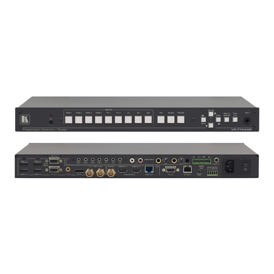
Page 13: Figure 1: Vp-774Amp Presentation Switcher/Scaler Front Panel
Figure 1: VP-774AMP Presentation Switcher/Scaler Front Panel Feature Function IR Receiver Accepts IR remote commands IR LED Lights red when the unit accepts IR remote commands INPUT Selector HDMI Press to select the HDMI input (from 1 to 4) Buttons... -
Page 14: Figure 2: Vp-774Amp Presentation Switcher/Scaler Rear Panel
Figure 2: VP-774AMP Presentation Switcher/Scaler Rear Panel Feature Function AUDIO IN HDMI 3.5mm Mini Jack Connect to an unbalanced audio source for audio takeover of the HDMI 1 to HDMI 4 embedded audio (see Unbalanced Section 6.3). The pinout is defined in Section 5.4... - Page 15 Connect to an SDI acceptor HDMI OUT Connect to an HDMI acceptor (from 1 to 2) VIDEO OUTPUT Connect to an HDBT receiver (for example, Kramer TP-580Rxr) to pass audio and video signals as well as HDBT OUT RJ-45 Connectors serial commands LINK LED...
-
Page 16: Installing In A Rack
Installing in a Rack This section provides instructions for rack mounting the unit. VP-774AMP - Installing in a Rack... -
Page 17: Connecting The Vp-774Amp
Alternatively, you can connect the DVI connector on the DVD player to the HDMI connector on the VP-774AMP via a DVI-HDMI adapter. You can connect the audio signal via the AUDIO IN HDMI 3.5mm mini jack, or use the embedded audio 2. - Page 18 You can also connect the HDMI OUT 2 output (not shown in Figure 10. Connect the HDBT RJ-45 connector to a receiver (for example, the Kramer TP-580Rxr). 11. Connect the AUDIO LINE OUT Terminal Block connector to a balanced...
-
Page 19: Figure 4: Connecting The Vp-774Amp Presentation Switcher/Scaler
Figure 4: Connecting the VP-774AMP Presentation Switcher/Scaler VP-774AMP - Connecting the VP-774AMP... -
Page 20: Wiring The Rj-45 Connectors
This section defines the TP pinout, using a straight pin-to-pin cable with RJ-45 connectors. Figure 5: TP PINOUT EIA /TIA 568B Wire Color Orange / White Orange Green / White Blue Blue / White Green Brown / White Brown VP-774AMP - Connecting the VP-774AMP... -
Page 21: Connecting The Balanced Stereo Audio Output
Audio Acceptor to the Balanced Output Microphone Pinout This section defines the microphone 6mm jack pinout. Figure 8: Microphone Pinout Audio Input Pinout This section defines the audio input 3.5mm jack pinout. Figure 9: Audio Input Pinout VP-774AMP - Connecting the VP-774AMP... -
Page 22: The Osd Menu
The OSD Menu The VP-774AMP OSD menu lets you set the operation parameters for the: Main Window Control PIP Window Control Entire System Control The nature of the operation setup appears in the OSD title, as shown in the... - Page 23 PIP window separately (by defining Window Control, see Section 6.8). General characteristics which apply to the entire system (for example, setting the volume) are changed without needing to shift control (the title line will state: Entire System Control). VP-774AMP - The OSD Menu...
- Page 24 Data is saved per window and per input (to a dedicated input + window memory), as applicable The control buttons let you control the VP-774AMP via the OSD menu. Press the: MENU (or ) button to enter the menu, exit the menu, and when in the OSD menu, move to the previous level and change menu settings in the OSD screen.
-
Page 25: The Input Menu
Input Source Select the input source: HDMI1, HDMI2, HDMI3, HDMI4, PC1, PC2, CV, DP or SDI Note that any change in the input source may cancel the freeze and blank settings. VP-774AMP - The OSD Menu... - Page 26 Use the front panel + and – buttons, IR remote control transmitter or Web page to set the position and height of the Main and/or PiP windows The PiP window maximum horizontal active image area is 1600 pixels VP-774AMP - The OSD Menu...
-
Page 27: Figure 11: Select The Display Mode
6.2.1.1 Changing the Size of the Main and/or PiP Window Use the H Width and V Height to change the size of the window using the + and – buttons on the front panel or remote control transmitter (as illustrated in Figure 12). VP-774AMP - The OSD Menu... -
Page 28: Figure 12: Changing The Size Of The Window
The following example shows how to increase the width of the window Figure 13: Increasing the Width 4. Select V Height (an OSD slide bar appears) and press + to increase the height, or – to decrease the height, see Figure VP-774AMP - The OSD Menu... -
Page 29: Figure 14: Increasing The Height
+ and – buttons on the front panel or remote control transmitter (as illustrated in Figure 15). Figure 15: Positioning the Window To move the position of the window, do the following: 1. Check that window control is set as required (for example, PiP Window Control). VP-774AMP - The OSD Menu... -
Page 30: Figure 16: Window Customization
An OSD slide bar appears: Figure 17: H-Position Slide Bar 4. Press the +/- buttons to move the PiP window horizontally. Use the V Position menu item in the same way to move the PiP vertically, Figure VP-774AMP - The OSD Menu... -
Page 31: Figure 18: Moving The Pip Window
Figure 18: Moving the PiP Window Note that the sequence in which you change the size and position of the window is insignificant, as long as you make sure that the resized image does not go beyond the window boundaries. VP-774AMP - The OSD Menu... -
Page 32: The Audio Menu
Mic1 volume without changing the Line out and Mic2 volume levels. In the Mix mode, set the: Line Mix [dB] – to decrease of the line out volume level without changing the Mic 1 and Mic 2 volume levels VP-774AMP - The OSD Menu... - Page 33 Set the SDI channeling for groups A, B, C and D to Activate CH1, Activate CH2 or Bypass. If other groups are set to Activate or Bypass, the remaining groups are read as None Set Bypassed channels to Unmute or Mute (see Section 6.3.1.1) VP-774AMP - The OSD Menu...
-
Page 34: Figure 20: Set The Output Volume Level
A and B are connected (CH1 and CH2 in group A are bypassed, CH1 in group B is bypassed and CH2 in group B is active). These channels are input to the Kramer 6810HDXL, processed and output to an audio acceptor: ... -
Page 35: Figure 21: Sdi Channeling Example
B as well as CH 1 and CH2 in group A (bypassed) are routed via the VP- 774AMP SDI output to the input of 6810HDXL; groups C and D are disconnected and therefore read as None (see example in Figure 21). VP-774AMP - The OSD Menu... -
Page 36: Figure 23: Sdi Channeling Example
If a channel in a disconnected group is activated, the system will automatically rearrange the groups and channel assignments to keep two groups connected and two others disconnected. VP-774AMP - The OSD Menu... -
Page 37: Figure 24: Sdi Bypassed Channels Menu
Select Bypass channels to set the bypassed channels to mute to cutoff the bypassed audio channels or to Unmute to let them pass through: Figure 24: SDI bypassed Channels Menu The Bypass Channels menu also lists the selected bypassed channels in the enabled groups. VP-774AMP - The OSD Menu... -
Page 38: The Process Menu
Set (from Level 1 to Level 5) Select the motion detection sensitivity for filtering of interlaced images. Set a high value for video where there is generally a large amount of motion, or a low value for little motion VP-774AMP - The OSD Menu... -
Page 39: The Picture Menu
Set the image color (back to its default values) and position per window (centers it correctly on the screen) See Auto Positioning menu item in Section 6.2 Note that Auto Adjust is disabled when in the Freeze state VP-774AMP - The OSD Menu... -
Page 40: The Enhance Menu
Block NR – as the level is set higher, the block noise disappears and the image appears softer Input noise reduction (except for Temporal NR) is enabled for interlaced video processing only and is inactive in the progressive scan. VP-774AMP - The OSD Menu... -
Page 41: The Scale Menu
If the native resolution is not supported by the selected Master Connection, the system searches for the best supported resolution. If the search fails (for example, if the master connection is disconnected or EDID is unreadable), the resolution will default to XGA. VP-774AMP - The OSD Menu... - Page 42 HDCP compliant, the VP-774AMP always outputs without HDCP and vice versa. Not that the VP-774AMP will output a green screen if the output acceptor to which it is connected is not HDCP compliant, in the case that the video on the Main or PiP window is HDCP encrypted.
- Page 43 By setting the output resolution to Native, the VP-774AMP is triggered to read the EDID of the main display and change the output resolution value according to the native resolution of the display.
-
Page 44: The Miscellaneous Menu
Blink – to On for the selected item in the OSD to blink, or Off Blink Period – to determine the blinking rate Timeout – to 30 seconds before OSD timeout, 60 seconds before OSD timeout or OFF (Off means that that the OSD appears continuously) VP-774AMP - The OSD Menu... - Page 45 (once restored, the buttons return to their normal function) When using the VP-774AMP for audio only, we recommend that you turn this feature off Luma Keying – to set the transparency level of the PIP window (see Section 6.8.1)
- Page 46 When the luma keying feature is On, any change in the setup (either by the user or by resetting due to a setup change) may cause the screen to flicker once. The luma keying will recover automatically after resetting. VP-774AMP - The OSD Menu...
- Page 47 1.0.pdf. The VP-774AMP intercepts XML files over the Ethernet in the CAP format via the dedicated EAS port from the alert generator server (for example, a FEMA server or a proprietary CAP message generation application) for immediate alert message triggering.
-
Page 48: Figure 30: Xml File Transfer
The Expiration Date field of the CAP XML file determines when the message will expire. Note that you can remove the message sooner by pressing/clicking any of the buttons on the VP-774AMP (front panel or remote control buttons, as well as via the Web page or protocol commands). - Page 49 To setup and activate the alert system on the VP-774AMP: 1. Set the dedicated EAS Ethernet connection port type and port number through which the VP-774AMP will be listening, as a client, to intercept alerts. By default, the dedicated EAS port settings are TCP, 5005. To change these setting see the “Emergency Alert Configuration”...
-
Page 50: The Display Modes
OSD menu. 7.1.1 Activating the Single Window Mode Set the VP-774AMP to the single window display mode in any of the following ways: Press and hold (for 3 seconds) the illuminated front panel PIP button until the button no longer illuminates ... - Page 51 If the HDMI signal is HDCP protected, it can appear on HDMI and HDBT outputs that are connected to supported HDCP compliant displays. However, it cannot appear on a display that is not HDCP compliant and will show a green screen instead. VP-774AMP - The Display Modes...
- Page 52 6. You can press the MENU button several times to exit the menu and save changes, or modify PiP window parameters via the other menu items. To return to Main Window control, repeat the procedure above but select Main Window in the Window Control submenu. VP-774AMP - The Display Modes...
-
Page 53: Figure 32: Cv Superimposed Over Dp
7.2.3 Selecting the PIP Source To select a PiP source you have to set the VP-774AMP to any of the PiP display mode configurations and then select the desired input. 7.2.3.1 Selecting the PiP Source via the Front Panel Buttons Press and hold the PIP front panel button while pressing the input button of the required PiP source. - Page 54 7. Scroll to the Input menu and press ENTER. 8. Select Input Source and press ENTER. 9. Choose the input for the PiP window. 10. Press the MENU a few times until you exit the OSD menu (changes are saved upon exit). VP-774AMP - The Display Modes...
-
Page 55: Controlling The Vp-774Amp
The infrared remote control transmitter (see Section 8.4) Controlling via the Front Panel Buttons The VP-774AMP includes the following front panel buttons: Input selector buttons for selecting the required input: HDMI (1 to 4), PC (1 and 2), CV, DP and SDI (see Section 8.1.1) -
Page 56: Controlling Via The Vp-774Amp Web Pages
Note that if the Protocol is set to Legacy (via the Miscellaneous menu, Section 6.8), the Web pages may not function properly. Make sure that your PC is connected via a network to the VP-774AMP and do the following: 1. Open your Internet browser. - Page 57 To connect to the VP-774AMP via RS-232, connect the RS-232 9-pin D-sub rear panel port on the VP-774AMP unit via a 9-wire straight cable (only pin 2 to pin 2, pin 3 to pin 3, and pin 5 to pin 5 need to be connected) to the RS-232 9-pin D-sub port on your PC.
-
Page 58: Figure 34: Local Area Connection Properties Window
6. Select Use the following IP Address, and fill in the details as shown in Figure 35. You can use any IP address in the range 192.168.1.1 to 192.168.1.255 (excluding 192.168.1.39) that is provided by your IT department. 7. Click OK. Figure 35: Internet Protocol (TCP/IP) Properties Window VP-774AMP - Controlling the VP-774AMP... - Page 59 8.3.3.2 Connecting the ETHERNET Port via a Network Hub (Straight- Through Cable) You can connect the Ethernet port of the VP-774AMP to the Ethernet port on a network hub or network router, via a straight-through cable with RJ-45 connectors. 8.3.3.3 Ethernet Port Configuration and Control Use the Kramer K-UPLOAD software to configure the VP-774AMP and the Web pages to control it via the Ethernet.
-
Page 60: Controlling Via The Infrared Remote Control Transmitter
Controlling via the Infrared Remote Control Transmitter You can control the VP-774AMP from the infrared remote control transmitter: Keys Function POWER Toggle the power save mode ON or OFF Enter the dual window mode (the latest setting), see Section 7.2... - Page 61 This distance can be extended to up to 60 meters when used with three extension cables (Model: C-A35M/A35F-50). Before using the external IR receiver, be sure to arrange for your Kramer dealer to insert the internal IR connection cable (P/N: 505-70434010-S) with the 3.5mm connector that fits into the REMOTE IR opening on the rear panel.
-
Page 62: Port Tunneling
Port Tunneling The port tunneling feature lets you send and receive simple RS-232 signals between a controller and a serial device via the VP-774AMP which is connected to the Ethernet and outputs via TP cable. The example, illustrated in Figure 37, shows a Kramer room controller that is connected to the VP-774AMP via the Ethernet. - Page 63 2. Set the HDBT UART command (the table in Section 12.4). By default, the settings are 9600,8,N,1 3. Make sure that the VP-774AMP is connected to Ethernet. The VP-774AMP is now ready to tunnel RS-232 signals via Ethernet port tunneling. VP-774AMP - Port Tunneling...
-
Page 64: Flash Memory Upgrade
Flash Memory Upgrade You can upgrade the VP-774AMP via the Kramer K-UPLOAD software. Two types of upgrade files are available for upgrade: video core and audio/graphics (*.fct) and peripherals (*.kfw). The latest firmware version, the Flash Memory Upgrade user guide, as... -
Page 65: Technical Specifications
19" (W), 9.3" (D) 1U (H) rack mountable WEIGHT: 2.5kg (5.5lbs) approx. Power cord, rack “ears”, IR remote control ACCESSORIES: Specifications are subject to change without notice For the most updated resolution list, go to our Web site at http://www.kramerelectronics.com VP-774AMP - Technical Specifications... -
Page 66: 11.1 Default Communication Parameters
Use “Factory” command or #Y 0,770,1<CR> Protocol 3000 11.2 Input Resolutions This section defines the input resolutions for each input 11.2.1 SDI Input Resolutions SDI Input Resolution NTSC 720_P60 1080_P24 1080_P50 1080_I50 1080_P25 1080_P60 720_P50 1080_I60 1080_P30 VP-774AMP - Technical Specifications... - Page 67 1024x768_85 1440x900_60 625_P50 1080_P25 800x600_56 1152x864_75 1400x1050_60 720_P24 1080_P30 800x600_60 1280x800_60 1400x1050_75 720_P25 1080_P50 800x600_72 1280x960_85 1600x900_60 720_P30 1080_P60 800x600_75 1280x768_60 1600x1200_60 720_P50 2K50 800x600_85 1280x1024_60 1680x1050_60 720_P60 2K60 848x480_60 1280x1024_75 1920x1200_60RB 1080_I50 640X480_60 1024x768_60 1280x1024_85 VP-774AMP - Technical Specifications...
-
Page 68: 11.3 Output Resolutions
1400x1050@60 720p59.94 2K60 1280x768@50 1600x900@60 720p60 1280x768@60 1600x1200@50 1080p23.976 1280x800@60 1600x1200@60 1080p24 11.3.2 SDI Output Resolutions Technical Specifications of the SDI Output Signal 480i60 720p60 1080p25 1080p50 576i50 1080p23.976 1080p29.97 1080p59.94 720p50 1080p24 1080p30 1080p60 720p59.94 VP-774AMP - Technical Specifications... -
Page 69: The Vp-774Amp Rs-232 Communication Protocol
® software (for example, the Windows HyperTerminal Application). 12.1 Using the Communication Protocol There are three different methods to control the VP-774AMP via the RS-232 or the Ethernet: Protocol commands (via protocol 3000 or Legacy Protocol) mimicking the OSD, see Section 12.2... - Page 70 For example, move the PiP window one step to the left Send: “#Y 0,141,-,1<CR>” Reply: “~01@Y 0,141,-,1 OK” For example, in order to increase zoom on the main window Send: “#Y 0,650,+,0<CR>” Reply: “~01@Y 0,650,+,0 OK” VP-774AMP - The VP-774AMP RS-232 Communication Protocol...
- Page 71 Process submenu (see also Section 6.1). When navigating in the OSD MENU you will be able to see the Film Mode valid parameters. The following table defines the protocol commands: VP-774AMP - The VP-774AMP RS-232 Communication Protocol...
- Page 72 8bpp, PM.EDID_SEL = 86h=134 dec 12bpp, PM.EDID_SEL = 6h=6 dec Color Space Applicable to PC and HDMI inputs YPbPr only Follow Input The value range is Window H Position 0:2048 dynamic. The FW Customization H Width 0:2048 VP-774AMP - The VP-774AMP RS-232 Communication Protocol...
- Page 73 Power Level 1 Power Level 2 Power Level 3 Power Level 4 Group A None 0 (read only) Channeling Activate CH1 Activate CH2 Bypass Group B None 0 (read only) Activate CH1 Activate CH2 VP-774AMP - The VP-774AMP RS-232 Communication Protocol...
- Page 74 Black Level -80:80 Gamma Mode Gamma Off Gamma 0.4 Gamma 0.8 Gamma 1.2 Gamma 1.6 Gamma 2.0 Gamma 2.4 Gamma 2.8 Dither Mode0: Disable error diffusion Mode1: In-frame 8:6 conversion Mode2: Intra-frame 8:6 conversion VP-774AMP - The VP-774AMP RS-232 Communication Protocol...
- Page 75 800x600@50 2. Special OSD 800x600@60 MENU screen, follow OSD 800x600@75 instructions 1024x768@50 1024x768@60 1024x768@75 1280x768@50 1280x768@60 1280x800@60 1280x1024@50 1280x1024@60 1280x1024@75 1360x768@60 1366x768@50 1366x768@60 1400x1050@50 1400x1050@60 1600x900@60 1600x1200@50 1600x1200@60 1680x1050@60 1920x1200@60 480i60 480p60 VP-774AMP - The VP-774AMP RS-232 Communication Protocol...
- Page 76 READ ONLY: In the OSD MENU - PALM Input, Output video PAL60 formats & FW version. N443 NTSC_4 In the protocol – SECAM Get command returns the Input video format only PALNC NTSC_8 VP-774AMP - The VP-774AMP RS-232 Communication Protocol...
- Page 77 720p25 720p30 1080i60 1080i50 1080i100 1080p60 1080p50 1080p30 1080p23_976 1080p24 1080p25 2K50 2K60 640X480@60 640x480@72 640x480@75 848x480@60 640x480@85 800x600@56 800x600@60 800x600@72 800x600@75 800x600@85 1024x768@60 1360x768@60 1280x768@60 1024x768@70 1024x768@75 1280x800@60 1024x768@85 1400x1050@60 1400x1050@75 1440x900@60 VP-774AMP - The VP-774AMP RS-232 Communication Protocol...
- Page 78 Luma Keying Volatile parameter. Screen may flicker. Keying the PiP window Alert System Pause Freeze Blank Mute In the PiP Mode, applies to main window only Disable Outputs Follow OSD instructions Protocol VP-774AMP - The VP-774AMP RS-232 Communication Protocol...
-
Page 79: Protocol Table: Mimicking Remote And Front Panel Buttons
12.4 The Protocol 3000 Common Operation Commands The following table lists the protocol 3000 commands: Operation commands Command Syntax Response Lock front panel LOCK-FP LOCK-MODE LOCK-FP LOCK-MODE RESULT Get front panel LOCK-FP? LOCK-FP LOCK-MODE locking state Parameters Description: VP-774AMP - The VP-774AMP RS-232 Communication Protocol... - Page 80 GET dedicated port PTNL-CFG? PTNL-CFG PORTTYPE, tunneling settings PORTNUM Parameters Description: either “TCP” or “UDP” PORTTYPE PORTNUM Ethernet port SET UART port tunneling UART BAUD, UART BAUD, DATA_BITS, settings DATA_BITS, PARITY, PARITY, STOPBITS RESULT VP-774AMP - The VP-774AMP RS-232 Communication Protocol...
- Page 81 "0" or "off" for single window. "1" or "on" to for dual window. Identification commands Command Syntax Response Protocol ~OK CRLF Handshaking Read device model MODEL? MODEL MACHINE_MODEL Read device serial SN SERIAL_NUMBER number VP-774AMP - The VP-774AMP RS-232 Communication Protocol...
- Page 82 1 – Try to use DHCP, if unavailable use IP as above. 2– Try to use DHCP, if unavailable use AUTO-IP as described here: http://support.microsoft.com/kb/q307287/ . Change ETH-PORT PROTOCOL , PORT ETH-PORT PROTOCOL ,PORT VP-774AMP - The VP-774AMP RS-232 Communication Protocol...
- Page 83 Response 2: LDFWS SIZE RESULT Load new Step 1: LDMFS SIZE audio/graphic Response 1: READY or LDMFS SIZE ERR### memory file Step 2: If ready was received, send FIRMWARE_DATA Response 2: LDMFS SIZE RESULT VP-774AMP - The VP-774AMP RS-232 Communication Protocol...
- Page 85 For the latest information on our products and a list of Kramer distributors, visit our Web site where updates to this user manual may be found. We welcome your questions, comments, and feedback. Web site: www.kramerelectronics.com E-mail: info@kramerel.com SAFETY WARNING...
Need help?
Do you have a question about the VP-774AMP and is the answer not in the manual?
Questions and answers