Advertisement
Quick Links
Technical guide
SCHEDA MB per ventilconvettori
MB BOARD for fan coils
CARTE MB pour ventilo-convecteurs
PLATINE MB für Klimakonvektoren
TARJETA MB para ventiladores convectores
MB KAART ventilators-convectors
October 2020
UNT-SVU011C-XX
Confidential and proprietary Trane information
Original instructions
Advertisement

Related Manuals for Trane UNT-SVU011C Series


Summary of Contents for Trane UNT-SVU011C Series
- Page 1 Technical guide SCHEDA MB per ventilconvettori MB BOARD for fan coils CARTE MB pour ventilo-convecteurs PLATINE MB für Klimakonvektoren TARJETA MB para ventiladores convectores MB KAART ventilators-convectors October 2020 UNT-SVU011C-XX Confidential and proprietary Trane information Original instructions...
- Page 2 INDICE CONTENTS Scopo Scope Configurazione Configuration Montaggio Mounting del gruppo di potenza the power assembly Scheda elettronica Electronic board Funzione Function dei contatti ausiliari of the auxiliary contacts Impostazione Setting Dip di configurazione the configuration dipswitches Tabella segnalazione LED LED signal table Configurazione di default Default configuration Funzione Autofan...
- Page 3 SOMMAIRE INHALT ÍNDICE INHOUD Zweckbestimmun Objetivo Doel Configuration Konfiguration Configuración Configuratie Montage Montage Montaje Montage du groupe de puissance der Leistungseinheit del grupo de potencia van de vermogensunit Carte électronique Elektronikplatine Tarjeta electrónica Elektronische fiche Fonction Funktion Función Functie des contacts auxiliaires der Hilfskontakte de los contactos auxiliares van de hulpcontacten...
- Page 4 CONFIGURAZIONE CONFIGURATION Il gruppo scheda-telecomando The board-remote control unit viene fornito con un kit compren- is supplied with a kit that includes sivo dei materiali illustrati a lato. the materials illustrated to the side. Dopo aver aperto e tolto l’imballo, After having opened and removed accertarsi che il contenuto sia quel- the packaging, make sure that the...
- Page 5 CONFIGURATION KONFIGURATION CONFIGURACIÓN CONFIGURATIE Le groupe carte-télécommande Die Einheit Platine-Fernbedienung El grupo tarjeta-mando a distancia De groep van kaart en afstands- bediening wordt geleverd in een est fourni avec un kit comprenant wird mit einem Set geliefert, das se entrega con un kit que incluye le matériel ci-contre.
- Page 6 MONTAGGIO MOUNTING DEL GRUPPO THE POWER DI POTENZA ASSEMBLY oIl Con oIl wIth otore sInCrono hree peed eloCItà synChronous otor a) Dalla spalla destra a) On the terminal block on the del ventilconvettore occorre, right shoulder of the fan coil, agendo sulla morsettiera, disconnect the wires scollegare i conduttori...
- Page 7 MONTAGE MONTAJE MONTAGE DU GROUPE MONTAGE DER DEL GRUPO VAN DE DE PUISSANCE LEISTUNGSEINHEIT DE POTENCIA VERMOGENSUNIT entIlo ConV aVeC lIMaKonVeKtor MIt oIl Con entIlatorluChtKoeler oteur synChrone synChronMotor MIt otor sínCrono synChrone à Itesses esChwIndIgKeIten eloCIdad otor Met nelheden a) A partir du côté droit a) Vom rechten Seitenteil des a) Desde el hombro derecho a) Op de rechterschouder...
- Page 8 MONTAGGIO MOUNTING DEL GRUPPO THE POWER DI POTENZA ASSEMBLY oIl Con oIl wIth otore lettronICo leCtronIC otor 2,9x19 2,9x19 UNT-SVU011C-XX...
- Page 9 MONTAGE MONTAJE MONTAGE DU GROUPE MONTAGE DER DEL GRUPO VAN DE DE PUISSANCE LEISTUNGSEINHEIT DE POTENCIA VERMOGENSUNIT entIlo ConVeCteur lIMaKonVeKtor MIt oIl Con entIlatorluChtKoeler aVeC oteur leKtronIsCheM otor leCtrónICo leKtroMotor leCtronIque otor UNT-SVU011C-XX...
- Page 10 SCHEDA ELECTRONIC ELETTRONICA BOARD 0/10V D0-D0 LEGENDA: KEY: D1 = Configuration dipswitches D1 = Dip Switch di configurazione D2 = Dip Switch di indirizzo D2 = Address dipswitches J1 = Jumper MC2 J1 = Jumper MC2 T1 = Sonda aria (posta T1 = Air probe (fitted in ripresa dell’apparecchio) at the appliance intake)
- Page 11 CARTE ELEKTRONIK- TARJETA ELEKTRONISCHE ELECTRONIQUE PLATINE ELECTRÓNICA FICHE Jumper J2 CHIUSO = Motore Asincrono CLOSED = Asynchronous Motor FERMEE = Moteur asynchrone GESCHLOSSEN = Asynchronmotor CERRADO = Motor Asíncrono GESLOTEN = Asynchrone Motor Jumper J2 APERTO = Motore ECM OPEN = ECM Motor OUVERT = Moteur ECM GEÖFFNET = Motor ECM ABIERTO = Motor ECM...
- Page 12 FUNZIONE FUNCTION DEI CONTATTI OF THE AUXILIARY AUSILIARI CONTACTS Contatto CA [F1-F1]: Contact CA [F1-F1]: ON-OFF remoto Remote ON-OFF oppure Change-Over or remote Summer/Winter Estate/Inverno remoto Change-Over (vedi impostazione DIP 9). (See DIP 9 setting). - con DIP N.ro 9 in OFF - with DIP No 9 set on OFF è...
- Page 13 FONCTION FUNKTION FUNCIONES FUNCTIE DES CONTACTS DE LOS CONTACTOS VAN DE AUXILIAIRES HILFSKONTAKTE AUXILIARES HULPCONTACTEN Contact CA [F1-F1]: Kontakt CA [F1-F1]: Contacto CA [F1-F1]: Contact CA [F1-F1]: MARCHE-ARRÊT à distance Fern-ON-OFF ON-OFF remoto ON-OFF remote of ou bien changement de marche oder Change-Over o bien Change-Over Omschakeling Zomer/Winter...
- Page 14 IMPOSTAZIONE SETTING THE DIP DI CONFIGURATION CONFIGURAZIONE DIPSWITCHES L'impostazione dei dip switches The dip switches configuration deve essere eseguita a mac- must be executed once the unit china priva di alimentazione. has been disconnected from the power supply. Posizione / Position / Position DEFAULT MPIANTO A TUBI...
- Page 15 EINSTELLUNG DER PROGRAMACIÓN INSTELLING PROGRAMMATION KONFIGURATIONS- CONFIGURATIE- DIPSWITCHES DIP-SWITCHES DE CONFIGURACIÓN SCHAKELAAR configuration Konfiguration La configuraciòn de los dip The dip switches configuration switches doit être efféctuée lor- Switches muss ausgeführt switches debe ser efectuada must be executed once the unit sque l'unité...
- Page 16 CONFIGURAZIONE DEFAULT DI DEFAULT CONFIGURATION - Ventilazione continua. - Fan always on. - Termostatazione (ON/OFF) del- - Temperature control (ON/OFF) le/a valvole/a acqua. on the water valve/valves. - T3 disattivata. - T3 disabled. Nota: la sonda T3 (di minima tem- Note: probe T3 (cut-out thermostat) peratura) è...
- Page 17 CONFIGURATION DEFAULT- CONFIGURACIÓN DEFAULT- PAR DEFAUT KONFIGURATION POR DEFECTO CONFIGURATIE - Ventilation continue. - Dauerbelüftung. - Ventilación continua. - Continue ventilatie. - Thermostatation (ON/OFF) de - Temperaturregelung (ON/OFF) - Control termostático (ON / OFF) - Thermostatische regeling (ON/OFF) la(des) vanne(s) eau. des Wasserventils/der Wasser- de la(s) válvula(s) agua.
- Page 18 FUNZIONE ANTI- ANTI- STRATIFICATION STRATIFICAZIONE FUNCTION (Jumper J5) (Jumper J5) (DEFAULT) Pin 1-2 = CHIUSO CLOSED FERME GESCHLOSSEN CERRADO GESTOLEN Configurazione Configuration recommended consigliata per installazioni VERTICAL VERTICALI. installations. Pin 2-3 = CHIUSO CLOSED FERME GESCHLOSSEN CERRADO GESTOLEN Configurazione Configuration recommended consigliata per installazioni HORIZONTAL ORIZZONTALI.
- Page 19 FONCTION FUNKTION ZUM FUNCIÓN ANTI- ANTI- SCHUTZ GEGEN ANTI- STRATIFICATIE STRATIFICATION LUFTSCHICHTUNG ESTRATIFICACIÓN FUNCTIE (Jumper J5) (Jumper J5) (Jumper J5) (Jumper J5) Configuration Empfohlene Configuración Aanbevolen conseillée pour installations Konfiguration bei Installationen aconsejada para instalaciones configuratie voor de installaties VERTICAL. VERTIKAL.
- Page 20 FUNZIONAMENTO MASTER-SLAVE MASTER-SLAVE OPERATION Gestione Managing di più apparecchi, a group of appliances, in collegamento seriale, via serial connection, con un unico telecomando with just one remote control o con il comando T–MB or with the T–MB control È possibile collegare più apparec- It is possible to connect multiple chi fra loro e controllarli simultanea- devices controlling them...
- Page 21 FONCTIONNEMENT MASTER-SLAVE- FUNCIONAMIENTO WERKING MAÎTRE-ESCLAVE FUNKTION MASTER-SLAVE MASTER-SLAVE Gestion Verwaltung Gestión Beheer de plusieurs appareils, von mehreren, seriell de más aparatos, van meer serieel aangesloten en raccordement série, geschalteten Geräten en conexión en serie, con apparaten, met een enkele avec une seule télécommande mit nur einer Fernbedienung un único mando a distancia afstandsbediening...
- Page 22 ISTRUZIONI OPERATING OPERATIVE PER INSTRUCTIONS IL COLLEGAMENTO FOR CONNECTION CON LINEA SERIALE VIA AN RS485 RS485 SERIAL LINE Nell’effettuare When making il collegamento elettrico the electrical connections di una rete di ventilconvettori in a network of fan coils utilizzanti la connessione communicating via a serial line, in via seriale, occorre extreme care must be paid to...
- Page 23 INSTRUCTIONS OPERATIVE INSTRUCCIONES AANWIJZINGEN POUR ANWEISUNGEN OPERATIVAS VOOR DE LE RACCORDEMENT FÜR DEN ANSCHLUSS PARA LA CONEXIÓN AANSLUITING AVEC LIGNE SÉRIE MIT SERIELLER CON LÍNEA EN SERIE MET SERIËLE LIJN RS485 LEITUNG RS485 RS485 RS485 Lors du raccordement Beim Elektroanschluss eines Al efectuar Voor de elektrische seriële électrique d’un réseau...
- Page 24 - non serrare eccessivamente - do not excessively tighten i conduttori sotto i morsetti the wires under the connection di collegamento terminale. terminals. Strip the end Spelare la parte terminale of the cable with care. del cavo con cura e attenzione. Do not crush the cable Non schiacciare il cavo in at the cable glands or safety...
- Page 25 - ne pas trop serrer - Die Leiter nicht zu stark - no apriete demasiado - zet de geleiders niet overdreven les conducteurs sous in den Anschluss-klemmen los conductores bajo las bornas aan in het klemmenbord. les bornes de raccordement. festziehen.
- Page 26 MESSA A TERRA EARTHING DELLA RETE THE NETWORK In fase When performing di collegamento seriale the serial connection between degli apparecchi, rispettare the appliances, follow la simbologia di collegamento: the connection symbols: - morsetto “D-” - terminal “D-” con morsetto “D-” with terminal “D-”...
- Page 27 MISE À LA TERRE ERDEN PUESTA A TIERRA AARDING DU RÉSEAU DES NETZES DE LA RED VAN HET NETWERK Au moment En la fase Bij de seriële aansluiting du raccordement série Beim seriellen Anschluss de conexión en serie van de apparaten, des appareils, respecter der Geräte de los aparatos, respete...
- Page 28 ACCESSORI ACCESSORIES Sonda T2 per Change-Over Change Over probe T2 Solamente sui ventilconvettori in Only on the fan coil units designed esecuzione per impianti a due tu- for two-pipe systems, the heating/ bi, la commutazione estate/inverno cooling changeover can be performed può...
- Page 29 ACCESSOIRES ZUBEHÖRE ACCESORIOS ACCESSOIRES Sonde T2 pour Change Over Fühler T2 für Change Over Sonda T2 para Change Over T2-sonde voor Change Over Seulement sur les ventilo-convecteurs Bei den Klimakonvektoren in 2-Leiter- Sólo en los ventiladores convectores Uitsluitend voor de ventilators-convectors pour installations à...
- Page 30 LEGENDA LEGEND = Motoventilatore = Fan = Scheda elettronica = Infra-red a infrarossi electronic board = Autotrasformatore = Autotransformer = Condensatore = Capacitor = Resistenza elettrica = Electrical heater = Elettrovalvola = Hot and cold acqua calda e fredda water valve (impianto a 2 tubi) (2-pipe system) = Elettrovalvola...
- Page 31 LÉGENDE LEGENDE LEYENDA LEGENDE = Motoventilateur = Motorventilator = Motoventilador = Motorventilator = Bornier IR = Platine IR = Tarjeta IR = Schakeling IR = Autotrasformateur = Spartransformator = Autotransformador = Autotransformator = Condensateur = Kondensator = Condensador = Condensator = Résistance électrique = Elektrischer Widerstand = Resistencia eléctrica...
- Page 32 SCHEMI CONNECTION DI COLLEGAMENTO DIAGRAMS oIl Con oIl wIth otore sInCrono hree peed eloCItà synChronous otor Impianto a 2 tubi / 2 pipe units Installation à 2 tubes / 2-Leiter-Anlage Instalación a 2 tubos / Installatie met 2 leidingen 230Vac 50Hz POMPA JP7B JP7A 230V...
- Page 33 SCHEMAS DE ESQUEMAS AANSLUIT- RACCORDEMENT SCHALTPLÄNE DE CONEXIÓN SCHEMA’S entIlo ConV aVeC lIMaKonVeKtor MIt oIl Con entIlatorluChtKoeler oteur synChrone synChronMotor MIt otor sínCrono synChrone à Itesses esChwIndIgKeIten eloCIdad otor Met nelheden Impianto a 4 tubi / 4 pipe units Installation à 4 tubes / 4-Leiter-Anlage Instalación a 4 tubos / Installatie met 4 leidingen 230Vac 50Hz POMPA...
- Page 34 SCHEMI CONNECTION DI COLLEGAMENTO DIAGRAMS oIl Con oIl wIth otore sInCrono hree peed eloCItà synChronous otor 230Vac 50Hz POMPA JP7B JP7A 230V 50Hz 6 speed CLOSED JP4A JP4B UNT-SVU011C-XX...
- Page 35 SCHEMAS DE ESQUEMAS AANSLUIT- RACCORDEMENT SCHALTPLÄNE DE CONEXIÓN SCHEMA’S entIlo ConV aVeC lIMaKonVeKtor MIt oIl Con entIlatorluChtKoeler oteur synChrone synChronMotor MIt otor sínCrono synChrone à Itesses esChwIndIgKeIten eloCIdad otor Met nelheden Impianto a 2 tubi 2 pipe units Installation à 2 tubes + T2 2-Leiter-Anlage Instalación a 2 tubos...
- Page 36 SCHEMI CONNECTION DI COLLEGAMENTO DIAGRAMS oIl Con oIl wIth otore lettronICo leCtronIC otor Impianto a 2 tubi / 2 pipe units Installation à 2 tubes / 2-Leiter-Anlage Instalación a 2 tubos / Installatie met 2 leidingen 230Vac 50Hz POMPA JP7B JP7A OPEN 230V 50Hz...
- Page 37 SCHEMAS DE ESQUEMAS AANSLUIT- RACCORDEMENT SCHALTPLÄNE DE CONEXIÓN SCHEMA’S entIlo ConVeCteur lIMaKonVeKtor MIt oIl Con entIlatorluChtKoeler aVeC oteur leKtronIsCheM otor leCtrónICo leKtroMotor leCtronIque otor Impianto a 4 tubi / 4 pipe units Installation à 4 tubes / 4-Leiter-Anlage Instalación a 4 tubos / Installatie met 4 leidingen 230Vac 50Hz POMPA JP7B JP7A...
- Page 38 SCHEMI CONNECTION DI COLLEGAMENTO DIAGRAMS oIl Con oIl wIth otore lettronICo leCtronIC otor 230Vac 50Hz POMPA JP7B JP7A OPEN 230V 50Hz JP4A JP4B UNT-SVU011C-XX...
- Page 39 SCHEMAS DE ESQUEMAS AANSLUIT- RACCORDEMENT SCHALTPLÄNE DE CONEXIÓN SCHEMA’S entIlo ConVeCteur lIMaKonVeKtor MIt oIl Con entIlatorluChtKoeler aVeC oteur leKtronIsCheM otor leCtrónICo leKtroMotor leCtronIque otor Impianto a 2 tubi 2 pipe units Installation à 2 tubes + T2 2-Leiter-Anlage Instalación a 2 tubos Installatie met 2 leidingen CHANGE OVER (T2) TH2O<30°C...
- Page 40 SCHEMI CONNECTION DI COLLEGAMENTO DIAGRAMS t-MB t-MB Impianto a 2 tubi resistenza elettrica 2 pipe units electric heater Installation à 2 tubes résistance électrique POWER GNYE GNYE SUPPLY 230Vac 50Hz 230V 50Hz 6 speed POWER SUPPLY 230Vac 50Hz ETTAGLIO COLLEGAMENTO ELETTRICO ETAIL DER ELEKTRISCHEN ERBINDUNG LECTRIC HEATER WIRING DETAIL...
- Page 41 SCHEMAS DE ESQUEMAS AANSLUIT- RACCORDEMENT SCHALTPLÄNE DE CONEXIÓN SCHEMA’S t-MB t-MB t-MB t-MB 2-Leiter-Anlage elektrischer Widerstand Instalación a 2 tubos resistencia eléctrica Installatie met 2 leidingen elektrische batterij GNYE POMPA JP7B JP7A CLOSED JP4A JP4B T-MB UNT-SVU011C-XX...
- Page 42 LOGICA OPERATING DI FUNZIONAMENTO LOGIC CON RESISTENZA WITH ELECTRICAL ELETTRICA HEATER — a — — a — CCessorIo CCessory I ventilconvettori possono essere The fans may be supplied with forniti con resistenza elettrica mon- electric resistance coil already tata e cablata in fabbrica. La resi- mounted and wired at the factory.
- Page 43 LOGIQUE DE LÓGICA DE FUNCTIONERINGS- FONCTIONNEMENT FUNKTIONSLOGIK FUNCIONAMIENTO LOGICA AVEC RESISTANCE MIT ELEKTRISCHER CON RESISTENCIA MET ELEKTRISCHE ELECTRIQUE WIDERSTAND ELÉCTRICA WEERSTAND — a — — z — — a — — a — CCessoIre uBehör CCesorIo CCessoIre Les ventilo.-convecteurs peuvent Die Ventilator-Konvektoren können ventiladores pueden...
- Page 44 SCHEMI CONNECTION DI COLLEGAMENTO DIAGRAMS teleCoMando InFra-red reMote Control Motore asInCrono asynChronous Motor Impianto a 2 tubi: funzionamento con resistenza elettrica quale elemento di riscaldamento principale. N.B.: non è possibile montare la sonda T3 su Fan Coil con resistenza elettrica. 2 pipe units: operation with electric resistance coil as main heating element.
- Page 45 SCHEMAS DE ESQUEMAS AANSLUIT- RACCORDEMENT SCHALTPLÄNE DE CONEXIÓN SCHEMA’S tÉlÉCoMMande FERNSTEUERUNG Mando por rayos AFSTANDS- InFrarroJos BEDIENING Moteur asynChrone synChronMotor Motor asínCrono asynChrone Motor ADDRESS CONFIGURATION UNT-SVU011C-XX...
- Page 46 SCHEMI CONNECTION DI COLLEGAMENTO DIAGRAMS CoMando t–MB a parete t–MB wall Control Motore asInCrono asynChronous Motor Impianto a 2 tubi: funzionamento con resistenza elettrica quale elemento di riscaldamento principale. N.B.: non è possibile montare la sonda T3 su Fan Coil con resistenza elettrica. 2 pipe units: operation with electric resistance coil as main heating element.
- Page 47 SCHEMAS DE ESQUEMAS SCHEMI RACCORDEMENT SCHALTPLÄNE DE CONEXIÓN DI COLLEGAMENTO CoMMande WANDSTEUERUNG Mando WANDMONTAGE Murale t–MB t–MB de pared t–MB CONTROLE t–MB Moteur asynChrone synChronMotor Motor asínCrono asynChrone Motor ADDRESS CONFIGURATION UNT-SVU011C-XX...
- Page 48 SCHEMI CONNECTION DI COLLEGAMENTO DIAGRAMS teleCoMando InFra-red + poMpa reMote Control + puMp Motore asInCrono asynChronous Motor Impianto a 2 tubi: funzionamento con resistenza elettrica quale elemento di riscaldamento principale. N.B.: non è possibile montare la sonda T3 su Fan Coil con resistenza elettrica. 2 pipe units: operation with electric resistance coil as main heating element.
- Page 49 SCHEMAS DE ESQUEMAS AANSLUIT- RACCORDEMENT SCHALTPLÄNE DE CONEXIÓN SCHEMA’S tÉlÉCoMMande FERNSTEUERUNG Mando por rayos AFSTANDS- + poMpe + puMpe InFrarroJos BEDIENING + BoMBa + POMP Moteur asynChrone synChronMotor Motor asínCrono asynChrone Motor ADDRESS CONFIGURATION UNT-SVU011C-XX...
- Page 50 SCHEMI CONNECTION DI COLLEGAMENTO DIAGRAMS CoMando t–MB a parete t–MB wall Control + poMpa + puMp Motore asInCrono asynChronous Motor Impianto a 2 tubi: funzionamento con resistenza elettrica quale elemento di riscaldamento principale. N.B.: non è possibile montare la sonda T3 su Fan Coil con resistenza elettrica. 2 pipe units: operation with electric resistance coil as main heating element.
- Page 51 SCHEMAS DE ESQUEMAS AANSLUIT- RACCORDEMENT SCHALTPLÄNE DE CONEXIÓN SCHEMA’S CoMMande WANDSTEUERUNG Mando WANDMONTAGE Murale t–MB t–MB de pared t–MB CONTROLE t–MB + poMpe + puMpe + BoMBa + POMP Moteur asynChrone synChronMotor Motor asínCrono asynChrone Motor ADDRESS CONFIGURATION UNT-SVU011C-XX...
- Page 52 SCHEMI CONNECTION DI COLLEGAMENTO DIAGRAMS teleCoMando InFra-red reMote Control Motore elettronICo eleCtronIC Motor Impianto a 2 tubi: funzionamento con resistenza elettrica quale elemento di riscaldamento principale. N.B.: non è possibile montare la sonda T3 su Fan Coil con resistenza elettrica. 2 pipe units: operation with electric resistance coil as main heating element.
- Page 53 SCHEMAS DE ESQUEMAS AANSLUIT- RACCORDEMENT SCHALTPLÄNE DE CONEXIÓN SCHEMA’S tÉlÉCoMMande FERNSTEUERUNG Mando por rayos AFSTANDS- InFrarroJos BEDIENING Moteur éleCtronIque leKtronIsCheM otor Motor eleCtrónICo eleKtroMotor ADDRESS CONFIGURATION UNT-SVU011C-XX...
- Page 54 SCHEMI CONNECTION DI COLLEGAMENTO DIAGRAMS CoMando t–MB a parete t–MB wall Control Motore elettronICo eleCtronIC Motor Impianto a 2 tubi: funzionamento con resistenza elettrica quale elemento di riscaldamento principale. N.B.: non è possibile montare la sonda T3 su Fan Coil con resistenza elettrica. 2 pipe units: operation with electric resistance coil as main heating element.
- Page 55 SCHEMAS DE ESQUEMAS SCHEMI RACCORDEMENT SCHALTPLÄNE DE CONEXIÓN DI COLLEGAMENTO CoMMande WANDSTEUERUNG Mando WANDMONTAGE Murale t–MB t–MB de pared t–MB CONTROLE t–MB Moteur éleCtronIque leKtronIsCheM otor Motor eleCtrónICo eleKtroMotor ADDRESS CONFIGURATION UNT-SVU011C-XX...
- Page 56 SCHEMI CONNECTION DI COLLEGAMENTO DIAGRAMS teleCoMando InFra-red + poMpa reMote Control + puMp Motore elettronICo eleCtronIC Motor Impianto a 2 tubi: funzionamento con resistenza elettrica quale elemento di riscaldamento principale. N.B.: non è possibile montare la sonda T3 su Fan Coil con resistenza elettrica. 2 pipe units: operation with electric resistance coil as main heating element.
- Page 57 SCHEMAS DE ESQUEMAS AANSLUIT- RACCORDEMENT SCHALTPLÄNE DE CONEXIÓN SCHEMA’S tÉlÉCoMMande FERNSTEUERUNG Mando por rayos AFSTANDS- + poMpe + puMpe InFrarroJos BEDIENING + BoMBa + POMP Moteur éleCtronIque leKtronIsCheM otor Motor eleCtrónICo eleKtroMotor ADDRESS CONFIGURATION UNT-SVU011C-XX...
- Page 58 SCHEMI CONNECTION DI COLLEGAMENTO DIAGRAMS CoMando t–MB a parete t–MB wall Control + poMpa + puMp Motore elettronICo eleCtronIC Motor Impianto a 2 tubi: funzionamento con resistenza elettrica quale elemento di riscaldamento principale. N.B.: non è possibile montare la sonda T3 su Fan Coil con resistenza elettrica. 2 pipe units: operation with electric resistance coil as main heating element.
- Page 59 SCHEMAS DE ESQUEMAS AANSLUIT- RACCORDEMENT SCHALTPLÄNE DE CONEXIÓN SCHEMA’S CoMMande WANDSTEUERUNG Mando WANDMONTAGE Murale t–MB t–MB de pared t–MB CONTROLE t–MB + poMpe + puMpe + BoMBa + POMP Moteur éleCtronIque leKtronIsCheM otor Motor eleCtrónICo eleKtroMotor ADDRESS CONFIGURATION UNT-SVU011C-XX...
- Page 60 SCHEMI CONNECTION DI COLLEGAMENTO DIAGRAMS teleCoMando InFra-red reMote Control Motore asInCrono asynChronous Motor Imp. a 2 tubi: funzionam. con resistenza elettrica quale elemento di integrazione. Attivazione della resistenza in funzione della temperatura acqua - rilevamento da sonda T2. N.B.: non è possibile montare la sonda T3 su Fan Coil con resistenza elettrica.
- Page 61 SCHEMAS DE ESQUEMAS AANSLUIT- RACCORDEMENT SCHALTPLÄNE DE CONEXIÓN SCHEMA’S tÉlÉCoMMande FERNSTEUERUNG Mando por rayos AFSTANDS- InFrarroJos BEDIENING Moteur asynChrone synChronMotor Motor asínCrono asynChrone Motor ADDRESS CONFIGURATION UNT-SVU011C-XX...
- Page 62 SCHEMI CONNECTION DI COLLEGAMENTO DIAGRAMS CoMando t–MB a parete t–MB wall Control Motore asInCrono asynChronous Motor Imp. a 2 tubi: funzionam. con resistenza elettrica quale elemento di integrazione. Attivazione della resistenza in funzione della temperatura acqua - rilevamento da sonda T2. N.B.: non è...
- Page 63 SCHEMAS DE ESQUEMAS SCHEMI RACCORDEMENT SCHALTPLÄNE DE CONEXIÓN DI COLLEGAMENTO CoMMande WANDSTEUERUNG Mando WANDMONTAGE Murale t–MB t–MB de pared t–MB CONTROLE t–MB Moteur asynChrone synChronMotor Motor asínCrono asynChrone Motor ADDRESS CONFIGURATION UNT-SVU011C-XX...
- Page 64 SCHEMI CONNECTION DI COLLEGAMENTO DIAGRAMS teleCoMando InFra-red + poMpa reMote Control + puMp Motore asInCrono asynChronous Motor Imp. a 2 tubi: funzionam. con resistenza elettrica quale elemento di integrazione. Attivazione della resistenza in funzione della temperatura acqua - rilevamento da sonda T2. N.B.: non è...
- Page 65 SCHEMAS DE ESQUEMAS AANSLUIT- RACCORDEMENT SCHALTPLÄNE DE CONEXIÓN SCHEMA’S tÉlÉCoMMande FERNSTEUERUNG Mando por rayos AFSTANDS- + poMpe + puMpe InFrarroJos BEDIENING + BoMBa + POMP Moteur asynChrone synChronMotor Motor asínCrono asynChrone Motor ADDRESS CONFIGURATION UNT-SVU011C-XX...
- Page 66 SCHEMI CONNECTION DI COLLEGAMENTO DIAGRAMS CoMando t–MB a parete t–MB wall Control + poMpa + puMp Motore asInCrono asynChronous Motor Imp. a 2 tubi: funzionam. con resistenza elettrica quale elemento di integrazione. Attivazione della resistenza in funzione della temperatura acqua - rilevamento da sonda T2. N.B.: non è...
- Page 67 SCHEMAS DE ESQUEMAS AANSLUIT- RACCORDEMENT SCHALTPLÄNE DE CONEXIÓN SCHEMA’S CoMMande WANDSTEUERUNG Mando WANDMONTAGE Murale t–MB t–MB de pared t–MB CONTROLE t–MB + poMpe + puMpe + BoMBa + POMP Moteur asynChrone synChronMotor Motor asínCrono asynChrone Motor ADDRESS CONFIGURATION UNT-SVU011C-XX...
- Page 68 SCHEMI CONNECTION DI COLLEGAMENTO DIAGRAMS teleCoMando InFra-red reMote Control Motore elettronICo eleCtronIC Motor Imp. a 2 tubi: funzionam. con resistenza elettrica quale elemento di integrazione. Attivazione della resistenza in funzione della temperatura acqua - rilevamento da sonda T2. N.B.: non è possibile montare la sonda T3 su Fan Coil con resistenza elettrica.
- Page 69 SCHEMAS DE ESQUEMAS AANSLUIT- RACCORDEMENT SCHALTPLÄNE DE CONEXIÓN SCHEMA’S tÉlÉCoMMande FERNSTEUERUNG Mando por rayos AFSTANDS- InFrarroJos BEDIENING Moteur éleCtronIque leKtronIsCheM otor Motor eleCtrónICo eleKtroMotor ADDRESS CONFIGURATION UNT-SVU011C-XX...
- Page 70 SCHEMI CONNECTION DI COLLEGAMENTO DIAGRAMS CoMando t–MB a parete t–MB wall Control Motore elettronICo eleCtronIC Motor Imp. a 2 tubi: funzionam. con resistenza elettrica quale elemento di integrazione. Attivazione della resistenza in funzione della temperatura acqua - rilevamento da sonda T2. N.B.: non è...
- Page 71 SCHEMAS DE ESQUEMAS SCHEMI RACCORDEMENT SCHALTPLÄNE DE CONEXIÓN DI COLLEGAMENTO CoMMande WANDSTEUERUNG Mando WANDMONTAGE Murale t–MB t–MB de pared t–MB CONTROLE t–MB Moteur éleCtronIque leKtronIsCheM otor Motor eleCtrónICo eleKtroMotor ADDRESS CONFIGURATION UNT-SVU011C-XX...
- Page 72 SCHEMI CONNECTION DI COLLEGAMENTO DIAGRAMS teleCoMando InFra-red + poMpa reMote Control + puMp Motore elettronICo eleCtronIC Motor Imp. a 2 tubi: funzionam. con resistenza elettrica quale elemento di integrazione. Attivazione della resistenza in funzione della temperatura acqua - rilevamento da sonda T2. N.B.: non è...
- Page 73 SCHEMAS DE ESQUEMAS AANSLUIT- RACCORDEMENT SCHALTPLÄNE DE CONEXIÓN SCHEMA’S tÉlÉCoMMande FERNSTEUERUNG Mando por rayos AFSTANDS- + poMpe + puMpe InFrarroJos BEDIENING + BoMBa + POMP Moteur éleCtronIque leKtronIsCheM otor Motor eleCtrónICo eleKtroMotor ADDRESS CONFIGURATION UNT-SVU011C-XX...
- Page 74 SCHEMI CONNECTION DI COLLEGAMENTO DIAGRAMS CoMando t–MB a parete t–MB wall Control + poMpa + puMp Motore elettronICo eleCtronIC Motor Imp. a 2 tubi: funzionam. con resistenza elettrica quale elemento di integrazione. Attivazione della resistenza in funzione della temperatura acqua - rilevamento da sonda T2. N.B.: non è...
- Page 75 SCHEMAS DE ESQUEMAS AANSLUIT- RACCORDEMENT SCHALTPLÄNE DE CONEXIÓN SCHEMA’S CoMMande WANDSTEUERUNG Mando WANDMONTAGE Murale t–MB t–MB de pared t–MB CONTROLE t–MB + poMpe + puMpe + BoMBa + POMP Moteur éleCtronIque leKtronIsCheM otor Motor eleCtrónICo eleKtroMotor ADDRESS CONFIGURATION UNT-SVU011C-XX...
- Page 76 MONTAGGIO MOUNTING DEL RICEVITORE THE RECEIVER (versioni ad incasso) (versions for built-in assembly) — a — — a — CCessorIo CCessory . 9066337 9066337 Fissare il ricevitore Fasten the receiver come mostrato in Figura “1”. as shown in Figure “1”. - Posizionare la dima e forare - Position the jig and drill (n°...
- Page 77 MONTAGE MONTAGE DES MONTAJE MONTAGE DU RECEPTEUR EMPFANGSTEILS DEL RECEPTOR ONTVANGER (versions encaissées) (Einbauversionen) (versiones (inbouwversie) para empotrar) — a — — z — — a — — a — CCessoIre uBehör CCesorIo CCessoIre 9066337 . 9066337 . 9066337 9066337 ód Fixer le récepteur Das Empfangsteil befestigen, wie...
- Page 78 BATTERIE BATTERIES Prima di effettuare qualsiasi Before performing any operations operazione con il telecomando, with the remote control, inserire le batterie a corredo. insert the batteries supplied. Le batterie Type AAA 1.5 Volt batteries che devono essere utilizzate must be used. sono di tipo AAA 1,5 Volt.
- Page 79 PILES BATTERIEN BATERÍAS BATTERIJEN Avant toute opération Bevor die Fernbedienung benutzt Antes de realizar cualquier ope- Alvorens de afstandsbediening avec la télécommande mettre wird, müssen die mitgelieferten ración con el mando a distancia, te gebruiken, worden de les piles fournies. Batterien eingesetzt werden.
- Page 80 NOTE GENERAL GENERALI NOTES Questo telecomando This remote control è a raggi infrarossi. uses infrared rays. Questo significa che, This means that, to send the per trasmettere i comandi control signals to the appliance, all’apparecchio, occorre puntare the remote control con il telecomando il ricevitore must be aimed at the receiver posto sul pannello frontale...
- Page 81 ALLGEMEINE NOTAS ALGEMENE NOTES ANMERKUNGEN GENERALES OPMERKINGEN Cette télécommande Diese Fernbedienung Este mando a distancia Deze afstandsbediening est à infrarouge. arbeitet mit Infrarotstrahlen. es de rayos infrarrojos. werkt met infraroodstraling. Cela signifie que, pour Dies bedeutet, dass die Fern- Esto significa que, para transmitir Dit betekent dat om de commando’s transmettre les commandes bedienung für die Übertragung...
- Page 82 Ogni volta che si vuole modificare Whenever the fan coil operating i parametri di funzionamento parameter need to be modified, del ventilconvettore occorre the instructions must be sent inviare le istruzioni premendo to the unit by pressing il tasto “ON/SEND”. the “ON/SEND”...
- Page 83 Pour modifier les paramètres Jedes Mal wenn die Betriebs- Cada vez que desee modificar Telkens wanneer men de fonctionnement de l’appareil parameter des Klimakonvektors los parámetros de funcionamiento de werkingsparameters van il faut envoyer les instructions verändert werden sollen, müssen del ventilador convector deberá...
- Page 84 IMPOSTAZIONE SETTING OROLOGIO THE CLOCK Impostazione dell’orologio Setting the clock del telecomando on the remote control e/o dell’apparecchio. and/or the appliance. 1 - Selezione 1 - Selecting modalità di funzionamento the operating mode - Premere il tasto SELECT: - Press the SELECT button: CLOCK SET CLOCK SET inizierà...
- Page 85 PROGRAMMATION EINSTELLUNG PROGRAMACIÓN INSTELLING HORLOGE DER UHR DEL RELOJ KLOK Programmation de l’horloge Einstellung der Uhr Programación del reloj Instelling klok de la télécommande der Fernbedienung del mando a distancia afstandsbediening et/ou de l’appareil. und/oder des Geräts. y/o del aparato. en/of apparaat.
- Page 86 IMPOSTAZIONE SETTING THE SET POINT SET DESIDERATO Premendo i pulsanti (+) o (-) Press the (+) or (-) button aumentare o diminuire il valore to increase or decrease della temperatura desiderata. the desired temperature value. Una volta impostato Once having set il valore desiderato, premere the desired value, press il tasto ON/SEND per trasmettere...
- Page 87 PROGRAMMATION EINSTELLUNG PROGRAMACIÓN INSTELLING DE LA TEMPERATURE DES GEWÜNSCHTEN VAN DE CONSIGNE VOULUE SOLLWERTS SET DESEADO GEWENSTE SET À l’aide des touches (+) ou (-) Durch Drücken Pulsando las teclas (+) o (-) Druk op de toetsen (+) en (-) augmenter ou diminuer der Tasten (+) und (-) den aumente o disminuya el valor...
- Page 88 IMPOSTAZIONE SETTING DELLA VENTILAZIONE THE FAN MODE Premere il pulsante FAN Press the FAN button to select per selezionare la modalità the desired fan operating speed: di ventilazione prescelta: low, medium, high or Automatic. ventilazione bassa, media, alta Once having selected o Automatica.
- Page 89 PROGRAMMATION EINSTELLUNG PROGRAMACIÓN INSTELLING DE LA VENTILATION DER BELÜFTUNG DE LA VENTILACIÓN VENTILATIE Appuyer sur la touche FAN Durch Drücken der Taste FAN Pulse el pulsador FAN Druk op de knop FAN pour sélectionner le mode den gewünschten Belüftungsmodus para seleccionar la modalidad om de gewenste ventilatiemodus de ventilation choisi: einstellen: niedrige, mittlere hohe...
- Page 90 MODALITÀ OPERATING DI FUNZIONAMENTO MODES Premere il pulsante MODE Press the MODE button per selezionare la modalità to select di funzionamento desiderata: the desired operating mode: - Ventilazione - Fan - Riscaldamento - Heating - Raffrescamento - Cooling - Automatico (una volta impostata - Automatic (once the desired la temperatura desiderata, l’ap- temperature has been set the...
- Page 91 MODE DE MODALIDAD DE FONCTIONNEMENT BETRIEBSMODUS FUNCIONAMIENTO WERKWIJZE Appuyer sur la touche MODE Mit der Taste MODE Pulse el pulsador MODE Druk op de knop MODE pour sélectionner den gewünschten para seleccionar la modalidad om de gewenste werkwijze le mode de fonctionnement voulu: Betriebs-modus wählen: de funcionamiento deseada: te selecteren:...
- Page 92 TIMER TIMER IMPORTANTE: IMPORTANT: se non vengono schiacciati tasti if no button is pressed per un tempo superiore for more than 10 seconds, a 10 secondi, il comando esce the remote control exits dal programma di impostazione the setting procedure e torna allo stato di riposo.
- Page 93 TIMER TIMER TIMER TIMER IMPORTANT: WICHTIG: IMPORTANTE: BELANGRIJK: si on n’appuie sur aucune touche, wenn für eine Dauer von mehr als si no se pulsan teclas durante indien langer dan 10 seconden au bout de 10 secondes 10 Sekunden keine Taste gedrückt un tiempo superior a 10 segundos, niet op de toetsen gedrukt wordt, la télécommande...
- Page 94 Impostazione Setting the STOP time: Ora di spegnimento: - Premere il tasto SELECT. - Press the SELECT button. La scritta PROGRAM & STOP The message lampeggiante PROGRAM & STOP apparirà sul display. will flash on the display. - Premere i tasti (+) o (-), - Press the (+) or (-) button;...
- Page 95 Programmation Heure d’arrêt: Einstellung der Ausschaltzeit: Programación Instelling Uitschakeluur: de la hora de apagado: - Appuyer sur la touche SELECT. - Die Taste SELECT drücken. - Pulse la tecla SELECT. - Druk op de toets SELECT. PROGRAM & STOP Am Display erscheint En la pantalla Het opschrift clignotesur l’afficheur.
- Page 96 T–MB COMANDO WALL-MOUNTED A PARETE T–MB CONTROLLER . 9066331E 9066331E – NOTE GENERALI – – GENERAL NOTES – T–MB è un comando The T–MB is a wall-mounted per installazione a parete controller that can be connected collegabile ad apparecchi cassette to fan coils fitted with the MB o ventilconvettori equipaggiati electronic board and connected...
- Page 97 COMMANDE WANDSTEUERGERÄT CONTROL COMMANDO MURALE T–MB T–MB DE PARED T–MB AAN WAND T–MB 9066331E . 9066331E . 9066331E 9066331E ÓD – NOTES – ALLGEMEINE – NOTAS – ALLGEMENE GENERALES – ANMERKUNGEN – GENERALES – AANTEKENINGEN – T–MB est une commande Das T–MB ist ein Steuergerät El T–MB es un control De T–MB is een commando...
- Page 98 INSTALLAZIONE CONTROL COMANDO INSTALLATION Separare la parte frontale del Separate comando dalla piastra posteriore the front of the controller premendo, con un cacciavite, from the rear plate by using la linguetta di bloccaggio a screwdriver to press posta sulla parte superiore the locking tongue del comando.
- Page 99 INSTALLATION STEUERGERÄT- INSTALACIÓN INSTALLATIE DE LA COMMANDE INSTALLATION CONTROL COMMANDO Retirer le capot avant Die Vorderseite des Steuergeräts Separar la parte frontal Het voorgedeelte de la commande en appuyant, durch Druck mit einem del control de la placa trasera van het commando scheiden à...
- Page 100 COLLEGAMENTI CONTROL ELETTRICI WIRING DEL COMANDO CONNECTIONS Il pannello comandi deve The control panel essere collegato elettricamente must be wired to the power board Main Board alla scheda di potenza posta located inside the all’interno dell’apparecchiatura electrical compartment of the elettrica dell’unità...
- Page 101 RACCORDEMENTS ELEKTRO- CONEXIONES ELEKTRISCHE ÉLECTRIQUES ANSCHLÜSSE DES ELÉCTRICAS VERBINDINGEN VAN DE LA COMMANDE STEUERGERÄTS DEL CONTROL HET COMMANDO Le panneau de commandes Das Steuerpult muss elektrisch La conexión eléctrica Het voorste paneel doit être branché électriquement an die Leistungskarte im Innern del tablero de mandos a la tarjeta moet elektrisch aangesloten à...
- Page 102 SETTING IMPOSTAZIONE DIP DIP SWITCHES L'impostazione dei dip switches The dip switches configuration eFault deve essere eseguita a mac- must be executed once the unit china priva di alimentazione. has been disconnected from the power supply. Il Blocco DIP può essere utiliz- Set DIP can be used to modify zato per modificare le funzioni the functions performed by...
- Page 103 PROGRAMMATION PROGRAMACIÓN DES DIPSWITCHES EINSTELLUNG DIP DEL DIP INSTELLING DIP configuration Konfiguration La configuraciòn de los dip The dip switches configuration switches doit être efféctuée lor- Switches muss ausgeführt switches debe ser efectuada must be executed once the unit sque l'unité a été débranchée werden, erst als die Einheit aus cuando la unidad està...
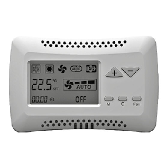
- Page 104 UTILIZZO USING DEL COMANDO THE CONTROL Fig. “A” / Abb. “A” On/Off (Fig. “A”): On/Off (Fig. “A”): • Premendo • Press il tasto ON/OFF the ON/OFF button il comando viene acceso. to activate the thermostat. • Premendo nuovamente • Press il tasto ON/OFF the ON/OFF button il comando viene spento.
- Page 105 UTILISATION GEBRAUCH DES GEBRUIK VAN DE LA COMMANDE STEUERGERÄTS DEL CONTROL HET COMMANDO On/Off (Fig. “A”): On/Off (Abb. “A”): On/Off (Fig. “A”): On/Off (Fig. “A”): • En appuyant • Durch Druck auf die • Si se presiona • Door op de toets sur la touche ON/OFF, Taste ON/OFF wird das el botón ON/OFF...
- Page 106 IMPOSTAZIONE SETTING OROLOGIO (Fig. “E”) THE CLOCK (Fig. “E”) Fig. “E” / Abb. “E” • Premere il tasto “M”: • By pressing the “M” button: il simbolo della modalità the mode symbol inizierà a lampeggiare. starts flashing. • Premere i tasti (+) o (-), •...
- Page 107 PROGRAMMATION EINSTELLUNG PROGRAMACIÓN INSTELLING HORLOGE (Fig. “E”) DER UHR (Abb. “E”) DEL RELOJ (Fig. “E”) KLOK (Fig. “E”) • Appuyer sur la touche “M”: • Drücken Sie die Taste “M”: • Presione la tecla “M”: • Druk op de toets “M”: le symbole du mode das Symbol des Modus el símbolo de la modalidad...
- Page 108 TIMER TIMER Fig. “F” / Abb. “F” 1) Attivazione / Disattivazione 1) Activation / Deactivation (Fig. “F”): (Fig. “F”): • Premere il tasto “M”; • Press the “M” button; il simbolo della modalità the operation mode di funzionamento symbol will start flashing. inizierà...
- Page 109 TIMER TIMER TIMER TIMER 1) Activation / Désactivation 1) Aktivierung / Deaktivierung 1) Activación / Desactivación 1) Inschakeling / Uitschakeling (Fig. “F”): (Abb. “F”): (Fig. “F”): (Fig. “F”): • Appuyer sur la touche “M”, • Drücken Sie die Taste “M“; •...
- Page 110 Fig. “G” / Abb. “G” 2) Programmazione 2) Programming (Fig. “G”): (Fig. “G”): • Premere il tasto “M”; • Press the “M” button; il simbolo della modalità the operation mode di funzionamento symbol will start flashing. inizierà a lampeggiare. • Premere il tasto (+) o (-) •...
- Page 111 2) Programmation 2) Programmierung 2) Programación 2) Programmering (Fig. “G”): (Abb. “G”): (Fig. “G”): (Fig. “G”): • Appuyer sur la touche “M”, • Drücken Sie die Taste “M“; • Presione la tecla “M”; • Druk op de toets “M”; le symbole du mode das Symbol el símbolo de la modalidad het symbool...
- Page 112 FUNZIONI FEATURES PER IL SERVICE FOR SERVICE Con questo menù This menu allows è possibile verificare alcuni verifying some parameters dei parametri del comando of the control (valore delle sonde, (probe values, stato del contatto finestra, window contact status, eventuali allarmi). any alarms).
- Page 113 CARACTERISTIQUES MERKMALE CARACTERÍSTICAS FUNCTIES POUR LE SERVICE FÜR BETRIEB DEL SERVICIO VOOR GEBRUIK Ce menu permet Dieses Menü gestattet Este menú permite In dit menu kunt vérification de certains die Überprüfung einiger la verificación de algunos u een aantal parameters paramètres du contrôle Parameter der Steuerung parámetros de control...
- Page 114 FUNZIONI PER IL FACTORY Questo menù consente di modificare i parametri di funzionamento del termostato, del motore elettronico, della versione +/- 3 e di altri vari parametri (ciclo pompa, RESET). > 3 sec. Con il comando in “OFF” premere i tasti M e Fan contemporaneamente per 3 secondi. Scegliere il parametro da modificare premendo i tasti “+”...
- Page 115 FEATURES FOR FACTORY This menu allows modifying the operation parameters of the thermostat, electronic motor, of the +/- 3 version and many other parameters (pump cycle, RESET). > 3 sec. With the control set on “OFF”, press the M and Fan buttons simultaneously for 3 seconds. Select the desired parameter to be modified, pressing button “+”...
- Page 116 CARACTÉRISTIQUES POUR L’USINE Ce menu permet de modifier les paramètres de fonctionnement du thermostat, moteur électronique, de la version +/- 3 et plusieurs autres paramètres (cycle de la pompe, RÉINITIALISATION). > 3 sec. Avec le réglage sur “OFF”, appuyer simultanément sur les touches M et Ventilation pendant 3 secondes.
- Page 117 MERKMALE FÜR DAS WERK Dieses Menü gestattet die Veränderung der Betriebsparameter des Thermostats, des elektronischen Motorsteuerung, der +/- 3 Version und viele weitere Parameter (Pumpzyklus, RESET). Mit der Steuerung auf “OFF” die M- und Fan-Taste > 3 sec. gleichzeitig für 3 Sekunden drücken. Wählen Sie durch Betätigung der “+”...
- Page 118 CARACTERÍSTICAS DE FÁBRICA Este menú permite modificar los parámetros de funcionamiento del termostato, electrónico del motor, de + / - 3 versiones y muchos otros parámetros (ciclo de bomba, RESET). Con el control en la posición “OFF”, presione > 3 sec. el botón M y Fan simultáneamente durante 3 segundos.
- Page 119 FABRIEKSFUNCTIES In dit menu kunt u de functioneringsparameters van de thermostaat, de elektromotor, de +/- 3 versie en verschillende andere parameters (pompcyclus, RESET) wijzigen. Druk met de bediening op “OFF” tegelijkertijd > 3 sec. 3 seconden lang op de knoppen M de Ventilator. Kies de gewenste parameter, druk op “+”...
- Page 120 DIMA DI FORATURA DRILLING JIG GABARIT DE PERCAGE BOHRSCHABLONE ESCANTILLÓN PARA PERFORAR BOORSJABLOON UNT-SVU011C-XX...
- Page 121 NOTES UNT-SVU011C-XX...
- Page 122 NOTES UNT-SVU011C-XX...
- Page 123 NOTES UNT-SVU011C-XX...
- Page 124 For more information, please visit trane.com or tranetechnologies.com. Trane has a policy of continuous product and product data improvement and reserves the right to change design and specifications without notice. We are committed to using environmentally conscious print practices.
Need help?
Do you have a question about the UNT-SVU011C Series and is the answer not in the manual?
Questions and answers