
Subscribe to Our Youtube Channel
Related Manuals for Trane VariTrane


Summary of Contents for Trane VariTrane
- Page 1 Installation/ Owner Programming VariT rane ™ Analog Electronic Controls For use with: Single-Duct Cooling & Reheat Units Parallel & Series Fan-Powered Units Low-Height Parallel & Series Fan-Powered Units VAV-SVX03A-EN November 2001...
- Page 2 © 2001 American Standard, Inc. All rights reserved VAV-SVX03A-EN...
-
Page 3: Table Of Contents
Contents General Information Literature Contents ....................4 Receiving and Handling ..................4 Unit Information Single-Duct Units ....................4-5 Fan-powered Units .................... 4-5 Analog Controls General Electonic Controls Installation Minimum and Maximum Potentiometers Adjustments Zone Sensor Wiring Location and Mounting Sequence of Operation Single-Duct Units .................... -
Page 4: General Information
This manual describes the operation, carrier. — Locate the nameplate and model calibration and set-up of VariTrane VAV — For re-heat units, check the coil fins and number and check that the correct units Single-Duct and Fan-powered units have been received. -
Page 5: Unit Information
Either straight flange or slip and drive is available with electric heat. The On a parallel unit, the VariTrane air electric heater is mounted on the damper delivers primary cooling air to discharge of the unit. Hot water coils the unit outlet. - Page 6 Unit Information Figure 2 – Typical Fan-Powered Units VSCF VSWF VSEF VPCF VPWF VPEF VAV-SVX03A-EN...
-
Page 7: Analog Controls
Insure that all jumpers are to the proper location and that the actual unit wiring matches the wiring diagram and wiring label information. See Figure 4. Electrical Data Units with electronic control options must use Trane zone sensors to be compatible INPUT : with the unit circuitry. The analog zone sensor electronics are designed 24 VAC, 50 VA maximum specifically to operate with the Trane electronic controls;... -
Page 8: Minimum And Maximum Potentiometers Adjustments
Analog Controls Figure 4 – Typical Analog Electronic Control Wiring Diagram Circuit Board Damage! Before handling the circuit board, discharge any static electricity you may have accumulated by touching the unit casing. Static charges produce voltages high enough to damage the electronic components. -
Page 9: Sequence Of Operation
Sequence of Operation Single-Duct Units Series Fan-Powered Untis Parallel Fan-Powered Units The air damper is controlled between The series fan-powered unit is a The parallel fan-powered unit is a minimum and maximum flow setpoints constant volume, variable temperature variable-volume, constant-temperature proportionally. -
Page 10: Control Options
Control Options Auto Dual Minimum CONTROL OPTIONS The auto dual minimum enables the Constant Volume unit to change the minimum automati- With this feature, when jack J15 Pin A is cally without an outside signal. The connected to Pin B, the electronics will minimum changes when the first stage cause the airflow to go to the maximum relay is activated. -
Page 11: Calibration
P PROCEDURE FOR controller. The first transition from flow input to the transducer. to voltage occurs at the Trane flow ring, MAXIMUM AND MINIMUM where a delta P signal is generated as a CALIBRATION function of airflow through the unit. -
Page 12: Set Minimum Flow
Calibration Set Minimum Flow(s) clockwise so that the amber light applied to the transducer. This will remains on with no delta P applied to In this section, two procedures for ensure that the unit will always go to the transducer. setting minimums will be discussed. -
Page 13: Balancing
Balancing a. Remove low-pressure cap from Balancing Procedure The following tools are required to test tee. properly adjust and calibrate the 1. Check the 24-volts AC supply voltage b. Remove high-pressure cap electronic controls: to the circuit card, terminals TB1-1 to from test tee. -
Page 14: Installation And Wiring
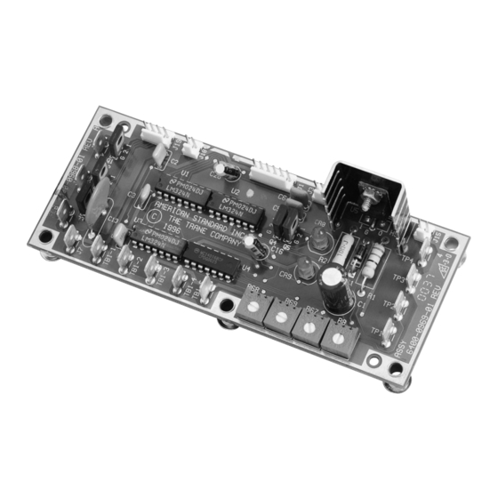
Installation and Wiring 1. Power is connected to TB1-1 and TB1- 7. There are various adjustments on the The general layout of the analog circuit 2. The power requirement is 24 volts circuit card as discussed in detail in the board is shown in Figure 5. -
Page 15: Zone Sensor
Zone Sensor Zone Sensor Operation terminal 3. With the voltages being equal, the room temperature is considered satisfied and all output relays are de-energized. If the temperature in the zone goes This section explains how the zone up, the resistance of the thermistor will go down, causing a voltage increase, which sensor operates. -
Page 16: Troubleshooting
Check calibration of zone sensor. See also calibration section. T ools and Equipment When repairing a VariTrane product (analog control), it is important to have the necessary tools and instruments. 1. 0-2" magnehelic gauge with fittings for two ¼" outside diameter (OD) tubing 2. -
Page 17: System Check
Troubleshooting 2. Be sure that there is proper voltage System Check Zone Sensor Check supplied by checking for 24 volts at Improper room control may be caused To troubleshoot the zone sensor, make terminal 1 and 2 on the circuit board. by areas other than the VAV boxes. -
Page 18: Transducer Check
Troubleshooting 7. If any step does not work, Fan Motor Check Triac Output Check replacement of the board may be 1. Make sure that the zone sensor To troubleshoot the fan motor, complete necessary. If all steps work, proceed operation is correct and, if applicable, the following procedure: with further component checks. -
Page 19: Electronic Zone Sensor Check
Troubleshooting 3. Slowly rotate the zone sensor until the 5. Check the voltage a terminals 2 (+) Electronic Zone Sensor amber LED on the circuit board and terminal 3 (-). If the zone Check illuminates. Voltage at terminal TP2 to temperature and the zone sensor ground should be approximately setpoint are at equilibrium, the voltage... - Page 20 La Crosse An American Standard Company www.trane.com Since The Trane Company has a policy of continuous product and product data improvement, it reserves the right For more information contact to change design specifications without notice. your local district office of Only qualified technicians should perform the installation and servicing of equipment referred to in this e-mail us at comfort@trane.com...
Need help?
Do you have a question about the VariTrane and is the answer not in the manual?
Questions and answers