Table of Contents
Advertisement
Quick Links
Advertisement
Table of Contents

Related Manuals for Gefen USB-500


Summary of Contents for Gefen USB-500
- Page 1 USB•500 U S E R M A N U A L www.gefen.com...
- Page 2 20600 Nordhoff St. Chatsworth, CA 91311 support@gefen.com www.gefen.com Gefen Inc. reserves the right to make changes in the hard ware, packaging and any accompanying doc u men ta tion without prior written notice. USB•500 is a trademark of Gefen Inc.
-
Page 3: Table Of Contents
TABLE OF CONTENTS General Information Introduction ... 1 Operation Notes ... 2 USB Series Installation ... 3 USB•500 Panel Layout ... 4 USB•500 Function Description ... 5 Wiring Diagram ... 6 Check List ... 7 Troubleshooting Hints ... 8 Warranty ... 9... -
Page 4: Introduction
INTRODUCTION Thank you for purchasing the ex•tend•it USB•500 Series. Incorporating ExtremeUSB, the new USB•500 model allows users the benefi ts of USB technology beyond the desktop, extending your computer keyboard, mouse, trackball, and any USB device up to 1650 feet away from the location of your Macintosh or PC computer. -
Page 5: Operation Notes
OPERATION NOTES READ THESE NOTES BEFORE INSTALLING OR OPERATING THE USB•500 SYSTEM. * The USB•500 units were designed to operate on USB type computers. DO NOT attempt to use this equip ment with any other type computers. * Use the computer's USB port when using a local keyboard that is not extended with the USB•500 sender unit. -
Page 6: Usb Series Installation
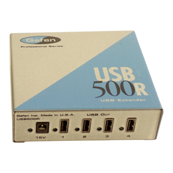
USB•500 SERIES INSTALLATION USB•500R (Receiver Unit) 1. Place the USB•500R unit close to the USB device to be served. 2. Connect the USB devices to the USB•500R unit. 3. Connect the power adapter to a suitable AC source wall outlet. 4. -
Page 7: Usb•500 Panel Layout
USB•500 PANELS LAYOUT USB•500S USB•500S Power USB•500R USB•500R Power USB 1 11 12 Link USB In Link USB 2 USB 3 USB 4 11 12 11 12... -
Page 8: Usb•500 Function Description
USB•500 FUNCTION DESCRIPTION Link LED Indicates a link between the USB•500S send and the USB•500R Receive units. Link MTRJ Modular Jack which connects to the USB•500S send and the USB•500R Receive units. Power LED Indicates the unit is plugged in and powered up. AC IN Power plug for +-15VDC Wallmount power supply. -
Page 9: Wiring Diagram
WIRING DIAGRAM... -
Page 10: Check List
CHECK LIST 1. On the USB•500S send unit, check that the power in di ca - tor is GREEN. 2. On the USB•500S send unit, check that the link indicator is GREEN. 3. On the USB•500R receiver unit, check that the power in di - ca tor is GREEN. -
Page 11: Troubleshooting Hints
TROUBLESHOOTING HINTS Power Indicator is not lit. -- Make certain the power supply unit is properly con nect ed to the USB•500R unit and the computers USB port is active and securely connected to the USB•500S Link Indicators are Green. -- Make certain that the host computer is operating and re- sponding to commands. -
Page 12: Warranty
If equipment fails because of such defects and Gefen Inc. is notifi ed within two (2) year from the date of shipment, Gefen Inc. will, at its option, repair or replace the equipment, provided that the equipment has not been subjected to mechanical, electrical, or other abuse or modifi...
Need help?
Do you have a question about the USB-500 and is the answer not in the manual?
Questions and answers