
Related Manuals for OLIMEX A20-OLINUXINO-LIME2-EMMC


Summary of Contents for OLIMEX A20-OLINUXINO-LIME2-EMMC
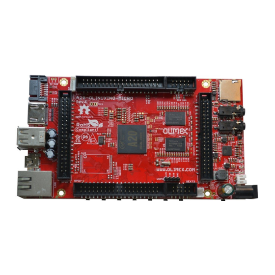
- Page 1 A20-OLinuXino-MICRO Open-source single-board Android/Linux mini-computer USER’S MANUAL Document revision P, December 2015 Designed by OLIMEX Ltd, 2015 All boards produced by Olimex LTD are ROHS compliant...
-
Page 2: Disclaimer
This document is intended only to assist the reader in the use of the product. OLIMEX Ltd. shall not be liable for any loss or damage arising from the use of any information in this document or any error or omission in such information or any incorrect use of the product. -
Page 3: Table Of Contents
OLIMEX© 2015 A20-OLinuXino-MICRO user's manual Table of Contents DISCLAIMER ......................2 CHAPTER 1: OVERVIEW ..................5 1. Introduction to the chapter ....................... 5 1.1 Features ............................. 5 1.2 Target market and purpose of the board ................6 1.3 Board variants .......................... 6 1.4 Board version used in the manual .................. - Page 4 OLIMEX© 2015 A20-OLinuXino-MICRO user's manual 5.3 Power supply circuit ......................23 CHAPTER 6: CONNECTORS AND PINOUT ............24 6. Introduction to the chapter ..................... 24 6.1 Communication with the A20 ....................24 6.1.1 USB-OTG communication (NAND firmware repair/update) ..............24 6.1.2 UART0, UEXT1, UEXT2 interface ......................
-
Page 5: Chapter 1: Overview
Thank you for choosing this OLinuXino single board computer from Olimex! This document provides a user’s guide for the Olimex A20-OLinuXino board. As an overview, this chapter gives the scope of this document and lists the board’s features. The document’s organization is then detailed. -
Page 6: Target Market And Purpose Of The Board
SD card. The 4GB version comes with already programmed Android 4.2.2 image. The other Olimex boards with close characteristics are the ones with A13 and A10 microcontrollers. The A13 boards feature a generation older processor but since they have been longer on the market they have better Linux and Android support. -
Page 7: Organization
OLIMEX© 2015 A20-OLinuXino-MICRO user's manual 1.5 Organization Each section in this document covers a separate topic, organized as follows: – Chapter 1 is an overview of the board usage and features – Chapter 2 provides a guide for quickly setting up the board and software notes –... -
Page 8: Chapter 2: Setting Up The Olinuxino Board
- Input device – either a mouse/keyboard or touchscreen LCD - Output device – either HDMI cable + native HDMI monitor/screen/projector; or USB-SERIAL- CABLE-F + personal computer (for Linux and/or Android debugging); or OLIMEX LCD (TS) display + 40-pin CABLE-IDC40-15cm; or A20-VGA-CABLE + VGA monitor/screen/projector - SD card with compatible image –... -
Page 9: Powering The Board
A20-Android-SD – a tested class 10 micro SD card with the latest (by the time of leaving the Olimex facilities) official Android release A20-Debian-SD – a tested class 10 micro SD card with the latest (by the time of leaving Olimex facilities) official Debian Linux release USB-SERIAL-CABLE-F –... -
Page 10: Prebuilt Software
USB OTG to USB type A cables if you lack such. The default username/password combination for the default Linux image on the SD card (if purchased) is: root/olimex. Note that it is normal that when the board is powered some integrated circuits might appear hotter than others. -
Page 11: Interacting With The Board
OLIMEX© 2015 A20-OLinuXino-MICRO user's manual VOL+ – increases the volume VOL- – lowers the volume MENU – brings up the main menu SEARCH – brings up search feature HOME – shows the home screen; note that HOME is also used to enter bootloader mode for firmware update ESC –... -
Page 12: Hdmi Monitor
OLIMEX© 2015 A20-OLinuXino-MICRO user's manual Using HDMI, LCD_CON or LAN might require additional configurations. Furthermore, it is possible to corrupt the output settings over those interfaces and, thus, lose the output. In such cases, you can always use the serial cable USB-SERIAL-CABLE-F as a reliable way to establish connection to the board. -
Page 13: Lcd Display
One of the ways to interact with the board is via an external display (with or without touchscreen component). The 40-pin male connector LCD_CON has the typical 0.1'' pin step. All Olimex displays have corresponding 40-pin male connector. You would only need a 0.1'' female-female cable for the hardware connection. - Page 14 9. 1080p50 10. 1080p60 For VGA: (note that the VGA signals are routed to custom 6 pin connector and you need to from adapter to standard VGA connector, Olimex also sells such adapter cables) 0. 1680×1050 1. 1440×900 2. 1360×768 3.
-
Page 15: Connecting And Calibrating A Display
All LCD displays made by Olimex have at least a 0.1'' LCD connector. Going for an LCD output you would also need need and a cable to attach the display to the board. The cable is sold separately. -
Page 16: Android Calibration
If the problem is under Debian Linux make sure you are properly logged in the LXDE interface! Else applying calibration would not happen for the current user – if you are calibrating from the X graphical interface make sure that you are logged as user “olimex” (if calibrating without the X, the user is “root”). -
Page 17: I2C And Spi Under Debian
We usually try to provide details on how to build the Linux and the Android images at our wordpress page: http://olimex.wordpress.com/. Another useful place is the Olimex forums where a lot of people share their experience and advice: https://www.olimex.com/forum/ Page 17 of 56... - Page 18 OLIMEX© 2015 A20-OLinuXino-MICRO user's manual Additional Android and Linux support and features are added overtime. The Linux support is a work-in-progress and you should not expect full Linux support after the initial volume of such boards have become available on the market. If you are in a hurry consider the older OLinuXino designs (which have almost everything supported, have examples available and so on).
-
Page 19: Chapter 3: A20-Olinuxino-Micro Board Description
OLIMEX© 2015 A20-OLinuXino-MICRO user's manual CHAPTER 3: A20-OLINUXINO-MICRO BOARD DESCRIPTION 3. Introduction to the chapter Here you get acquainted with the main parts of the board. Note the names used on the board might differ from the names used below to describe them. For the actual names check the A20- OLinuXino-MICRO board itself. -
Page 20: Layout (Bottom View)
OLIMEX© 2015 A20-OLinuXino-MICRO user's manual 3.2 Layout (bottom view) At the bottom of the board there are mainly buttons and the large SD/MMC connector. Page 20 of 56... -
Page 21: Chapter 4: The Allwinner A20 Embedded Processor
OLIMEX© 2015 A20-OLinuXino-MICRO user's manual CHAPTER 4: THE ALLWINNER A20 EMBEDDED PROCESSOR 4. Introduction to the chapter In this chapter is located the information about the heart of OLinuXino – its microcontroller. The information is a modified version of the datasheet provided by its manufacturers. -
Page 22: Block Diagram
OLIMEX© 2015 A20-OLinuXino-MICRO user's manual AUDIO Integrated HI-FI 100dB Audio Codec Dual analog mic amplifiers More information can be found on Allwinner's web site at the following web-address: http://www.allwinnertech.com/en/product/A20.html 4.2 Block diagram The block diagram is taken from Allwinner's web-site. -
Page 23: Chapter 5: Control Circuity
OLIMEX© 2015 A20-OLinuXino-MICRO user's manual CHAPTER 5: CONTROL CIRCUITY 5. Introduction to the chapter Here you can find information about reset circuit and quartz crystals locations, the power supply circuit is discussed. 5.1 Reset The board has hardware reset controlled by the AXP209 power system management IC. -
Page 24: Chapter 6: Connectors And Pinout
OLIMEX© 2015 A20-OLinuXino-MICRO user's manual CHAPTER 6: CONNECTORS AND PINOUT 6. Introduction to the chapter In this chapter are presented the connectors that can be found on the board all together with their pinout and notes about them. Jumpers functions are described. Notes and info on specific peripherals are presented. - Page 25 OLIMEX© 2015 A20-OLinuXino-MICRO user's manual 5. Connect USB cable to the mini USB connector 6. You will be asked for drivers for the bootloader. Navigate to the folder where you extracted the PhoenixSuit and install the drivers from the respective executables (or manually point the installer to the drivers folder in the PhoenixSuit installation path).
-
Page 26: Uart0, Uext1, Uext2 Interface
7 SPI1-MISO SPI1-MOSI 9 SPI1-CLK SPI1-CS0 The UEXT connectors are used as an interface for the Olimex's UEXT modules (usually boards with MOD- prefix in their commercial names). For more information on UEXT please visit: https://www.olimex.com/Products/Modules/UEXT/resources/UEXT.pdf Page 26 of 56... -
Page 27: Sd Card Connectors
When in doubt – try the same operation with another card from another brand. Olimex sells microSD cards with Linux or Android images, that have been tested – please refer to chapter “2.2 Requirements”. Of course, if you already have a large enough microSD card you can download the official Linux image from the wiki pages: https://www.olimex.com/wiki/A20-... -
Page 28: Sd/Mmc1 Slot
OLIMEX© 2015 A20-OLinuXino-MICRO user's manual 6.2.1 SD/MMC1 slot The schematic related to the SD/MMC1 (microSD connector) is shown below: SD/MMC1 slot is the “smaller” microSD card slot, located on the top of the board. This slot is typically used for booting the OS, due to the larger capacities of the microSD cards (compared to SD or MMC cards). -
Page 29: Sd/Mmc Slot
OLIMEX© 2015 A20-OLinuXino-MICRO user's manual 6.2.2 SD/MMC slot The schematic related to the SD/MMC1 (SD/MMC connector) is shown below: The SD/MMC2 slot is located on the back of the PCB and works with the “larger” SD and MMC cards. The connector was placed by a popular demand. -
Page 30: Pwr Jack
6.3 PWR jack The power jack used is the typical one used by Olimex in most of our products – the DC barrel jack has 2.0mm inner pin and 6.3mm hole. More information about the exact component might be found here: https://www.olimex.com/wiki/PWRJACK. -
Page 31: Usb_Otg Connector
OLIMEX© 2015 A20-OLinuXino-MICRO user's manual MIC_IN. The MIC_IN is a mono input. MIC_IN connector Pin # Signal name Processor pin MICIN AC20 MICIN AC20 The socket can interface standard 3.5 mm phone connector (also known stereo plug or audio plug). - Page 32 OLIMEX© 2015 A20-OLinuXino-MICRO user's manual There are two parts of a successful OTG device/host mode switch and usage – hardware part and software part. The hardware part is the cable – to use the OTG as a host you would need a mini USB to USB adapter cable.
-
Page 33: Usb_Host Connector
OLIMEX© 2015 A20-OLinuXino-MICRO user's manual 6.6 USB_HOST connector The part of the schematic related to the USB_HOST connector is listed below: The USB_HOST connector features two levels – called USB1 and USB2 in the schematic. The connector is situated between the USB_OTG and the HDMI connector. Each of slots them features a low loss power distribution switch SY6280 which protects the board in case the devices you have plugged to each level USB_HOST try to draw more than the allowed current. -
Page 34: Ethernet
OLIMEX© 2015 A20-OLinuXino-MICRO user's manual USB_HOST two-level connector Pin # Signal name Processor pin Pin # Signal name Processor pin Connected to SY628 Connected to SY628 UDM1 UDM2 UDP1 UDP2 The GND is common for both levels of the USB_HOST. - Page 35 OLIMEX© 2015 A20-OLinuXino-MICRO user's manual Important: In some Debian images it is possible that the Ethernet doesn't get auto-detected during boot-up. This is done on purpose because if there is auto-detection enabled and you don't want to use the Ethernet connector or you have forgotten to plug a cable the start-up would be greatly delayed.
-
Page 36: Hdmi Connector
OLIMEX© 2015 A20-OLinuXino-MICRO user's manual 6.8 HDMI connector The part of the schematic that describes the HDMI module is shown below: Note that there are different Linux images depending whether the HDMI TV works at 50Hz or 60Hz refresh rate. If you board runs Android there is a specific option to set the appropriate HDMI output. -
Page 37: Vga Connector
6.9 VGA connector You would probably need an adapter cable for the VGA display (6-pin connector to 15-pin female RGB cable). You can make the cable or the connection yourself or you can purchase the Olimex- made cable: https://www.olimex.com/Products/Components/Cables/A20-VGA-CABLE/.Note that you also have to change the script under Debian as explained in chapter 2.6 “Calibrating a display”. -
Page 38: Sata Connector And Power
OLIMEX© 2015 A20-OLinuXino-MICRO user's manual 6.10 SATA connector and power The part of the schematic describing the SATA module is shown below: SATA connector Pin # Signal name Processor pin SATA-TXP SATA-TXM SATA-RXM SATA-RXP Page 38 of 56... -
Page 39: Gpio Ports
OLIMEX© 2015 A20-OLinuXino-MICRO user's manual 6.11 GPIO ports There are three GPIO ports which are used generally to access unused by the board's peripherals pins. However, there are exceptions – some of the pins might be used to easily peripherals or their levels. -
Page 40: Gpio-2 (General Purpose Input/Output) 40Pin Connector
OLIMEX© 2015 A20-OLinuXino-MICRO user's manual 6.11.2 GPIO-2 (General Purpose Input/Output) 40pin connector The GPIO pins are led out on a separate 40pin connecter. They allow the user to attach additional hardware, check readings or perform hardware debug. The GPIO-2 connector numbers are printed at the bottom of the board for your convenience. -
Page 41: Gpio-3 (General Purpose Input/Output) 40Pin Connector
OLIMEX© 2015 A20-OLinuXino-MICRO user's manual 6.11.3 GPIO-3 (General Purpose Input/Output) 40pin connector GPIO-3 connector features the signals of AXP152 on a convenient header. The signals available might be used to implement power controls on the board – for instance – turning off the device at specific voltage level or detecting levels. - Page 42 The real issue would be finding piece of software that has Allwinner A20 support. The sunxi community has some experimental configuration files for A10 and A13 boards I believe, but they were never tested by an Olimex employee. Furthermore, we have no experience with the JTAG debug, we have not performed any JTAG debug sessions ourselves.
-
Page 43: Lcd_Con 40Pin Connector
We have tested the ability of the board to interact with such a display. They allow the user to attach additional hardware, check readings or perform hardware debug. Important: you need additional 40PIN ribbon cable to connect an Olimex display and the LCD_CON. -
Page 44: Jumper Description
OLIMEX© 2015 A20-OLinuXino-MICRO user's manual The LCD connector is suitable for a number of Olimex displays and touchscreen panels with different native resolution – the smallest available is the 4.3'' one called LCD-OLinuXino-4.3TS with native screen resolution of 480×272, through the 7'' one named LCD-OlinuXino-7TS with 800×480, to the 1024×600 10.1'' LCD-OLinuXino-10TS. -
Page 45: Additional Hardware Components
OLIMEX© 2015 A20-OLinuXino-MICRO user's manual 6.14 Additional hardware components The components below are mounted on OLinuXino but are not discussed above. They are listed here for completeness: Reset button – used to reset the board 1GB = 2×[4Gb(256M x 16b)] DDR3 SDRAM – the exact memory used currently in the board is SAMSUNG K4B4G1646D-BCK0 The DDR3 memory part name in the schematic might be outdated. -
Page 46: Chapter 7: Schematics
OLIMEX© 2015 A20-OLinuXino-MICRO user's manual CHAPTER 7: SCHEMATICS 7. Introduction to the chapter In this chapter is located information about the schematics describing logically and physically A20- OLinuXino-MICRO. 7.1 Eagle schematic OLinuXino schematics may be found it on the OLinuXino's GitHub repository: https://github.com/OLIMEX/OLINUXINO/tree/master/HARDWARE/A20-OLinuXino-MICRO. -
Page 47: Physical Dimensions
OLIMEX© 2015 A20-OLinuXino-MICRO user's manual 7.2 Physical dimensions Note that all dimensions are in mils. The three highest elements on the board in order from the tallest to the shortest are: USB_HOST connector – 700mils, capacitors C202 – 650mils, the Ethernet connector – 600mils. -
Page 48: Chapter 8: Revision History And Support
OLIMEX© 2015 A20-OLinuXino-MICRO user's manual CHAPTER 8: REVISION HISTORY AND SUPPORT 8. Introduction to the chapter In this chapter you will find the current and the previous version of the document you are reading. Also the web-page for your device is listed. Be sure to check it after a purchase for the latest available updates and examples. - Page 49 2. Added GPIO, I2C and SPI sections 3, 13, 14, 34, 35, 36, J, 03.11.14 3. Added information about newer 37, 44 Olimex A20 boards boards 4. Added board revision G changes 5. Fixed few spelling mistakes 1. Updated list of suggested displays K, 30.01.2015 8, 27, 46 2.
-
Page 50: Board Revision
OLIMEX© 2015 A20-OLinuXino-MICRO user's manual 8.2 Board revision Remember to check the schematics and the board design files to compare the differences. Revision Notable changes Initial release of the board 1. Resistor matrix RM23 gets replaced by: R133,R134,R135 2. Adjusted the package of H5TQ2G63BFR/MEM4G16D3EABG-125 3. -
Page 51: Useful Web Links And Purchase Codes
A20-Android-SD – a tested class 10 micro SD card with the latest (by the time of leaving the Olimex facilities) official Android release A20-Debian-SD – a tested class 10 micro SD card with the latest (by the time of leaving Olimex facilities) official Debian Linux release LCD-OLinuXino-4.3TS –... -
Page 52: Frequently Asked Questions
OLIMEX© 2015 A20-OLinuXino-MICRO user's manual 8.4 Frequently asked questions Q: I power my board, it shows a logo and then nothing happens. A: This might be due to a number of reasons but it is recommended to try the following: 1. - Page 53 OLIMEX© 2015 A20-OLinuXino-MICRO user's manual Q: How to detect and enable the Ethernet controller (if it is disabled by default)? A: You can enable it by following these two steps: 1. To check under what name the LAN is associated write "ifconfig –a"...
- Page 54 OLIMEX© 2015 A20-OLinuXino-MICRO user's manual Q: I have a 4GB version of the board. The board doesn't seem to have Android loaded. A: We no longer load Android on the NAND memory of the boards. You can upload Android following the advice above in this document.
- Page 55 OLIMEX© 2015 A20-OLinuXino-MICRO user's manual Android will go in sleep mode and you have to press POWER button to start it, you can change to fast boot when you power off there is dialog box asking you if you want next boot to be fast boot, you have to check this box before you power off.
-
Page 56: Product Support
All goods are checked before they are sent out. In the unlikely event that goods are faulty, they must be returned, to OLIMEX at the address listed on your order invoice. OLIMEX will not accept goods that have clearly been used more than the amount needed to evaluate their functionality.
Need help?
Do you have a question about the A20-OLINUXINO-LIME2-EMMC and is the answer not in the manual?
Questions and answers