Table of Contents
Advertisement
Quick Links
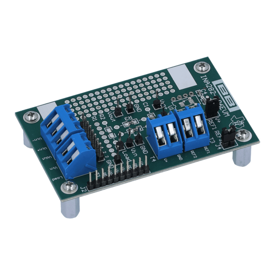
This user's guide describes the characteristics, operation, and use of the INA282-286EVM evaluation
module (EVM). This EVM is designed to evaluate the performance of the
output current shunt monitors. This EVM has a flexible configuration, allowing for user evaluation suitable
to a variety of applications. This document also includes a schematic and a complete bill of materials.
1
2
3
4
5
6
1
2
3
4
5
6
7
8
9
10
11
12
13
14
15
INA282-286EVM Schematic
All trademarks are the property of their respective owners.
SBOU083 - September 2010
Submit Documentation Feedback
.................................................................................................
................................................................................................
....................................................................................................
.................................................................................................
.............................................................................................
.............................................................................................................
List of Figures
..................................................................................................
...............................................................................................
.....................................................................................................
.........................................................................................................
.....................................................................................................
.....................................................................................................
......................................................................................................
.............................................................................................
.............................................................................................
Copyright © 2010, Texas Instruments Incorporated
INA282-INA286EVM
Contents
...........................................................................
....................................................
..................................................
......................................................
.................................................................
User's Guide
SBOU083 - September 2010
INA282-286
family of voltage
......................
INA282-INA286EVM
2
4
6
10
13
14
3
4
5
6
6
6
6
8
9
10
11
11
12
12
13
1
Advertisement
Table of Contents

Related Manuals for Texas Instruments INA282-286EVM


Summary of Contents for Texas Instruments INA282-286EVM
-
Page 1: Table Of Contents
User's Guide SBOU083 – September 2010 INA282-INA286EVM This user’s guide describes the characteristics, operation, and use of the INA282-286EVM evaluation module (EVM). This EVM is designed to evaluate the performance of the INA282-286 family of voltage output current shunt monitors. This EVM has a flexible configuration, allowing for user evaluation suitable to a variety of applications. -
Page 2: Introduction And Overview
The INA282-286EVM allows the user to install a shunt resistor, and then connect both the common-mode voltage and load to develop the input voltage, or to omit the shunt resistor and apply a differential voltage directly to the device input. -
Page 3: Hardware Included With The Ina282-286Evm
Introduction and Overview www.ti.com Hardware Included The INA282-286EVM features the SOIC-packaged version of the INA28x. Device boards populated with each of the available gain versions of the INA282 family of devices will be provided in all INA282-286EVM delivered, as Figure 1 shows. -
Page 4: Quick Start Setup And Use
Quick Start Setup and Use Follow these procedures to set up and use the INA282-286EVM. Step 1. Insert the device board to be evaluated into the U1 location. The U1 location allows the user to either evaluate one of the provided device boards or to install the test device directly on the surface-mount pads in the U1 footprint. -
Page 5: Measurement Without Shunt
This connection method allows the user to either simulate the voltage developed across a sense resistor based on a given set of system conditions, or to connect the INA282-286EVM remotely to an existing shunt already included in an example application. -
Page 6: Ina282-286Evm Circuit
INA282-286EVM Circuit This section summarizes the INA282-286EVM components. R1 can be used for shunt resistors that have a package that is not easily adaptable to a standard, two-terminal, through-hole footprint or to a 0603 through 1206 surface-mount footprint. Specifically, this component location was added to allow for the use of TO-126, TO-220, TO-247, and four-terminal inline radial packages such as the CS3 series of shunts from Ohmite. - Page 7 INA282-286EVM Circuit www.ti.com Figure 6. TO-126 Package in R1 Figure 7. TO-220 Package in R1 SBOU083 – September 2010 INA282-INA286EVM Submit Documentation Feedback Copyright © 2010, Texas Instruments Incorporated...
-
Page 8: Radial Package In R2
J1 is intended to be used as measurements points of R1, if necessary. J2 is used as a test port at the factory but can be used for the corresponding input and output pins, if desired. INA282-INA286EVM SBOU083 – September 2010 Submit Documentation Feedback Copyright © 2010, Texas Instruments Incorporated... -
Page 9: U1 Populated With Dip Board
INA282-286EVM Circuit www.ti.com U1 is the location for the test device. Five device boards are supplied with this INA282-286EVM board; each device board is populated with one of the available device gains. This interchangeable option allow users to test the devices and determine the gain setting that is best suited for a given application. -
Page 10: Reference Voltage Setup
Miscellaneous The REF1 and REF2 terminals of T3 allow the user to configure the INA282-286EVM for either unidirectional or bi-directional operation. Two easily-accessed oscilloscope ground pads are located on the PCB to facilitate easier probing. -
Page 11: Unidirectional Mode: Negative Differential Voltage Configuration
(based on the internal voltage divider) is a mid-supply reference voltage. REF1 REF2 Figure 12. Bi-directional Mode: One Reference to Ground, One Reference to Supply Configuration SBOU083 – September 2010 INA282-INA286EVM Submit Documentation Feedback Copyright © 2010, Texas Instruments Incorporated... -
Page 12: Bi-Directional Mode: Specific Voltage Required Configuration
REF1 REF3020 2.048V Reference REF2 £ Figure 13. Bi-directional Mode: Specific Voltage Required Configuration REF1 REF2 £ Figure 14. Bi-directional Mode: Buffered Voltage Configuration INA282-INA286EVM SBOU083 – September 2010 Submit Documentation Feedback Copyright © 2010, Texas Instruments Incorporated... -
Page 13: Ina282-286Evm Schematic
Vout Scope GND2 GND1 GND2 LOGO1 INA282-286 Vin - Burr Brown Products GND3 Vin - 0.1uF LOGO2 REF2 Burr Brown Products REF2 Figure 15. INA282-286EVM Schematic SBOU083 – September 2010 INA282-INA286EVM Submit Documentation Feedback Copyright © 2010, Texas Instruments Incorporated... -
Page 14: Bill Of Materials
Bill of Materials www.ti.com Bill of Materials Table 2 provides the parts list for the INA282-286EVM. Table 2. INA282-286EVM Bill of Materials Count RefDes Value Description Manufacturer Part Number Optional/ Not Installed Optional/ Resistor, 0603-1206/Through-Hole Not Installed R3, R4 0Ω... - Page 15 Evaluation Board/Kit Important Notice Texas Instruments (TI) provides the enclosed product(s) under the following conditions: This evaluation board/kit is intended for use for ENGINEERING DEVELOPMENT, DEMONSTRATION, OR EVALUATION PURPOSES ONLY and is not considered by TI to be a finished end-product fit for general consumer use. Persons handling the product(s) must have electronics training and observe good engineering practice standards.
- Page 16 IMPORTANT NOTICE Texas Instruments Incorporated and its subsidiaries (TI) reserve the right to make corrections, modifications, enhancements, improvements, and other changes to its products and services at any time and to discontinue any product or service without notice. Customers should obtain the latest relevant information before placing orders and should verify that such information is current and complete.
Need help?
Do you have a question about the INA282-286EVM and is the answer not in the manual?
Questions and answers