
Related Manuals for Onset EG4100 Series


Summary of Contents for Onset EG4100 Series
- Page 1 EG4xxx Owner’s Manual Version 1.0 Onset Computer Corp 470 MacArthur Blvd Bourne, MA 02532 www.onsetcomp.com 800-564-4377 loggerhelp@onsetcomp.com April 18, 2018...
-
Page 2: Installation
EG4xxx Owner’s Manual 2 INSTALLATION 1 Introduction Thank you and congratulations to your purchase of an Onset EG4xxx device! Properly installed, the device will be able to record and report energy usage and production for years to come. The first and second section of this manual describes installation and commis- sioning of the product. -
Page 3: Materials Required For Installation
2 INSTALLATION EG4xxx Owner’s Manual 2.2 Materials required for installation Per phase: Use of proper smallest available breakers or rated fuse taps for the install per local NEC rules. Usually 15A circuit breaker or single multi- pole breaker depending on phases used. Black, red, and white stranded AWG 12 wire;... -
Page 4: Safety Warnings
EG4xxx Owner’s Manual 2 INSTALLATION Throughout the rest of this document, we use the term “phase” to refer both to the phases of 3-phase power distribution as well as the two legs used in split-phase power distribution. The following table describes the symbols used on the device: Symbol: Description: Caution, risk of danger. -
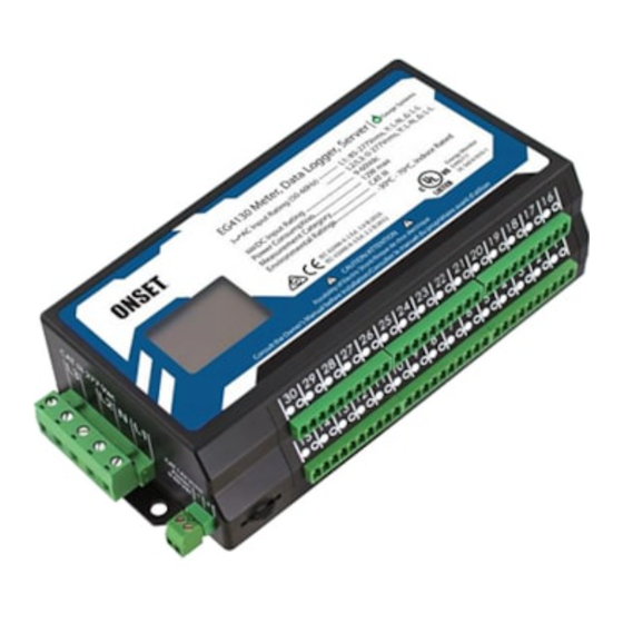
Page 5: Device Overview
2 INSTALLATION EG4xxx Owner’s Manual The EG4xxx is permanently connected equipment. A 15A circuit-breaker shall be included (one per phase) in close proximity of the device and within easy reach of the operator. The breakers shall be marked as the disconnecting device for EG4xxx. - Page 6 EG4xxx Owner’s Manual 2 INSTALLATION The unit also has an Ethernet port (RJ45 connector) which can be used to hard- wire the device to a Local Area Network (LAN). It also has two USB ports (Type- A Female) to interface to various other IT devices. An LCD shows a basic user interface with readouts from the set variable registers.
- Page 7 2 INSTALLATION EG4xxx Owner’s Manual Figure 3: AC Mains Connector Pin: Name: Description: Wire to phase 1 of building supply. Wire to building’s Neutral. Wire to phase 2 of building supply for split- and three-phase installs. Unused. Leave unconnected. Wire to phase 3 of building supply for three-phase installs. The AC Mains Connector is CAT III rated (for measurements performed in the building installation, such as circuit breakers).
- Page 8 EG4xxx Owner’s Manual 2 INSTALLATION Figure 4: DC Connector Pin: Name: Description: Wire to DC signal. Wire to ground. The DC Connector CAT III rated for use from -60 – 60Vdc. It can measure the voltage across that full range but if powered by the DC port, there must be at least 9Vdc.
- Page 9 2 INSTALLATION EG4xxx Owner’s Manual The CT Connector is rated for wiring one to thirty units of the CTs listed in Sec- tion B.6. The input voltage rating is 0.333Vrms at the rated current. NOTE: There is no risk of damage if a CT plug is accidentally inserted such that it straddles the pins for two different CTs.
- Page 10 EG4xxx Owner’s Manual 2 INSTALLATION The USB ports are USB2.0 compatible and can supply up to 1A at 5V. They may be used with various supported IT devices such as RS485-to-USB converters or WiFi adapters. 2.7.6 Multi-switch Figure 7 is a close-up of the multi-switch. The user can slide the switch Left or Right for navigation and push the switch into the unit to select.
-
Page 11: Wiring Diagram
2 INSTALLATION EG4xxx Owner’s Manual data item was recorded prior to the power failure. The proper time must then be restored later on, either manually via the device’s Settings Date & Time page or by provisioning an NTP server that is accessible. 2.8 Wiring Diagram 2.8.1 Typical Residential (Split-Phase) Installation Figure 8 is a schematic wiring diagram showing a typical split-phase installation... -
Page 12: Installation Steps
EG4xxx Owner’s Manual 2 INSTALLATION 2.9 Installation steps 1. If you are planning on using the hard-wired Ethernet port, skip to Step 3. (a) Find a spot at the installation site that has both an available power outlet and a nearby Ethernet port (for access to the LAN). (b) Plug the HomePlug AV adapter into the outlet. - Page 13 3 COMMISSIONING EG4xxx Owner’s Manual Figure 9: Correct wiring for 2-pin CT plug If it is necessary to shorten or lengthen the CT wires, ensure that the CT wires are connected as shown in Figure 9. 8. Close the newly installed breakers. This should cause the EG4xxx to power up and, within a few seconds, the LCD will illuminate and show a logo.
-
Page 14: Operation
EG4xxx Owner’s Manual 4 OPERATION Use a laptop or another computer to connect to the device’s built-in web-server (see next section). Then, as described in the Configuration Guide, Tools Chan- nel Checker can be used to confirm that: 1. All voltages have the expected values (use voltage meter to verify). 2. - Page 15 4 OPERATION EG4xxx Owner’s Manual For example, to access device Onset9999, you would enter the following URL into your browser: Microsoft Windows: http://onset9999/ All other computers: http://onset9999.local/ You may also use the LCD display to find the local IP address of the EG4xxx on the network.
- Page 16 EG4xxx Owner’s Manual 4 OPERATION Figure 10: EG4xxx dashboard April 18, 2018...
-
Page 17: Configuring A Static Ip Address
4 OPERATION EG4xxx Owner’s Manual NOTE: From time to time, the address of your EG4xxx may change and the bookmark will stop working. Should this happen, repeat the above steps and update the bookmark with the new address. Usually, this happens infrequently, if at all. -
Page 18: Maintenance
EG4xxx Owner’s Manual 5 MAINTENANCE upper-right hand menu on the EG4xxx main interface. Credentials and remote administration can be managed in Settings Access Control. 5 Maintenance The EG4xxx is designed to be maintenance free. No preventive maintenance or inspections are required. Should it become necessary to clean the EG4xxx, disconnect it from the building supply by turning off the breakers labeled “EG4xxx Meter Disconnect”, remove the device, and clean it with a soft cloth. -
Page 19: Fcc Compliance Statement
A EMI COMPLIANCE EG4xxx Owner’s Manual A EMI Compliance A.1 FCC Compliance Statement This equipment has been tested and found to comply with the limits for a Class B digital device, pursuant to part 15 of the FCC Rules. These limits are designed to provide reasonable protection against harmful interference in a residential installa- tion. - Page 20 EG4xxx Owner’s Manual B SPECIFICATIONS B Specifications B.1 Applicable Model Numbers This manual applies to all EG4xxx models ranging from EG4000 through EG4999. B.2 Electrical Rating of the Product AC Mains Connector: 85-277Vrms, 1-3 phases, 50-60 Hz, 12W peak (2W typical).
-
Page 21: C Troubleshooting
C TROUBLESHOOTING EG4xxx Owner’s Manual B.6 Current Transformers (CT) The EG4xxx is a Listed Device, certified to be used with Listed CTs. The CTs sold by the manufacturer have been evaluated to ensure correct performance. The current sensors may not be installed in a panel where they exceed 75% of the wiring space of any cross-sectional area within the panel, in accordance with NEC sections such as 312.8 and 366.9, as well as Articles 300 and 408. - Page 22 EG4xxx Owner’s Manual C TROUBLESHOOTING C.1 Default Installation Checklist The EG4xxx needs to be configured for the environment it is installed in. Most EG4xxx will have default settings for two 100A CTs monitoring Grid in CT ports 1 and 2, and a 50A CT monitoring L1 of the solar inverter in CT3. The installa- tion information sheet included with the EG4xxx will have the default configura- tion printed on it.
- Page 23 D INSTALLATION INFORMATION EG4xxx Owner’s Manual D Installation Information Device Location: Device Name: Voltage Configuration: Device Login: Device Password: Notes: April 18, 2018...
- Page 24 EG4xxx Owner’s Manual D INSTALLATION INFORMATION CT # CT Model Phase Measured item April 18, 2018...
Need help?
Do you have a question about the EG4100 Series and is the answer not in the manual?
Questions and answers