Table of Contents
Advertisement
Quick Links
H
O
B
O
H
O
B
O
®
®
U
3
0
N
R
C
U
3
0
N
R
C
(
N
o
R
e
m
o
t
e
(
N
o
R
e
m
o
t
e
C
o
m
m
u
n
i
c
a
t
C
o
m
m
u
n
i
c
a
t
onset
®
i
o
n
)
i
o
n
)
User's Guide
© 2008 Onset Computer Corporation. All rights reserved.
Onset, HOBO, and HOBOware are trademarks or registered trademarks of
Onset Computer Corporation for its data logger products and
configuration/interface software.
All other trademarks are the property of their respective companies.
Onset Computer Corporation
470 MacArthur Blvd.
Bourne, MA 02532
Part #: MAN-U30-NRC
Doc #: D-11866-A
Advertisement
Table of Contents

Subscribe to Our Youtube Channel
Related Manuals for Onset HOBO U30 NRC


Summary of Contents for Onset HOBO U30 NRC
- Page 1 ® User’s Guide © 2008 Onset Computer Corporation. All rights reserved. Onset, HOBO, and HOBOware are trademarks or registered trademarks of Onset Computer Corporation for its data logger products and configuration/interface software. All other trademarks are the property of their respective companies.
-
Page 2: Contact Information
Hours of Operation: 8 AM to 5 PM ET, Monday through Friday loggerhelp@onsetcomp.com E-mail: Main Onset Web site: www.onsetcomp.com If you purchased the products through an Onset Authorized Dealer, you can also refer to www.hobohelp.com for support information. HOBO U30 Station (NRC) User’s Guide HOBO U30 Station (NRC) User’s Guide... -
Page 3: Table Of Contents
Replacing the Battery ..............43 Key Features ................2 Chapter Five: Maintenance ............ 45 HOBO U30 NRC Station Components ........3 General Maintenance ..............45 Smart Sensors ................6 Inspecting the HOBO U30 Station ..........46 ... - Page 4 Supplementary Information ............71 Warranty ..................72 Returns ..................74 Repair Policy ................75 Contacting Technical Support............ 76 HOBO U30 Station (NRC) User’s Guide HOBO U30 Station (NRC) User’s Guide...
-
Page 5: Chapter One: Overview
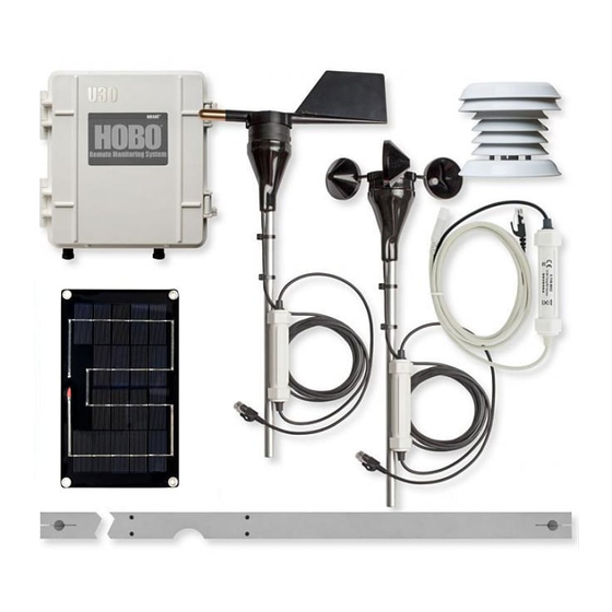
The HOBO U30 Station can be optionally configured with an Analog Sensor The HOBO U30 Station package includes: Port, which includes two user-configurable inputs that can accept and provide excitation power to a wide range of Onset and third-party sensors • HOBO U30 Station with 0-20 V or 0-20 mA output. -
Page 6: Hobo U30 Nrc Station Components
HOBO U30 NRC Station Components Component Descriptions Item Description 1. LED There are three Light Emitting Diode (LED) status indicators. Logging indicates whether the system is currently logging. Alarm indicates if an alarm has been tripped. Sensor active indicates that Smart Sensor network communications are occurring. -
Page 7: Smart Sensors
Sensors. Smart Sensors 9. Battery A 4-volt sealed lead-acid (SLA) battery is located behind the internal enclosure. Smart Sensor Cable Length 10. Battery connector Plug in the 4-volt sealed lead-acid battery The HOBO U30 Station can work with a maximum total of Smart Sensor here. -
Page 8: The Analog Sensor Port (Optional)
HOBO U30 Station. This two-channel port can accept, and provide excitation power to a wide range of Onset and third-party sensors with 0–20 V or 0–20 mA output, including devices with 4–20 mA current loop interface, and sensors with 0–... -
Page 9: Chapter Two: Initial Setup And Test
2. Install Mounting Plates (page 10) 3. Connect Smart Sensors (page 11) and Analog Sensors (page 13). Onset recommends that you test all sensors you plan to deploy with the logger. If you are using the Solar Radiation Shield, set up the Temperature and Temperature/RH sensors. -
Page 10: Connecting Smart Sensors
Primary Cable Slots Connecting Smart Sensors 1. Run cables for Smart Sensors through the Primary Cable Opening. NOTE: Connect Smart Sensors before you begin logging with the U30. 2. Plug the cables into the primary Smart Sensor ports. Smart Sensors plugged in after logging has already begun will be ignored. Secondary Cable Slots Before You Begin This procedure assumes that the Smart Sensor Expander Board and... -
Page 11: Connecting Analog Sensors
Connecting Analog Sensors Connecting the Battery Refer to the sensor documentation for sensor connection details and use the Connect the built-in battery cable to the battery. pin out diagram below to connect a two- or three-wire sensor or transducer NOTE: As long as your battery has adequate charge, you do not need to to the module’s terminals. -
Page 12: Connecting The U30 To A Computer
Connecting the U30 to a Computer Connecting the U30 to HOBOware Pro To connect to a computer running HOBOware Pro, plug the “mini-B” end of To connect the U30 to HOBOware Pro: the USB cable provided into the USB port on the HOBO U30 Station and 1. -
Page 13: Configuring The Analog Sensor Port
3. In the Select Device pane, click in the circle next to the desired Configuring the Analog Sensor Port device name and then click OK. This topic provides the basic steps for configuring the analog sensor port. See the HOBOware User Guide for complete details. Steps To configure an Analog Sensor Port, perform the following steps: 1. - Page 14 3. Select a channel and then click the Configure button. The Configure Channel window appears. NOTE: The default channel names are just place holders. Either channel can be configured to measure voltage or current. For example, both channels can be used to monitor sensors with 4-20 mA output.
-
Page 15: Launching The U30 Nrc
2. Complete fields as required. Launching the U30 NRC Description: Enter a description if desired. 1. Click the Launch icon on the toolbar to display the Launch window. Channels to Log: Make sure all of the sensors connected to the logger are visible in the Channels to Log pane. -
Page 16: Checking The U30 Status
2. Verify Sensor Readings Checking the U30 Status Change the sensor readings by changing the conditions. 1. From the main menu go to Device > Status to open the Status window. For example, if you are measuring temperature, hold the temperature sensor in your hands for a minute or two and verify that the temperature shown in the Current Readings increases. -
Page 17: Reading Out The U30 Nrc
5. Stop Logging Reading Out the U30 NRC Once you are satisfied everything is working properly, stop the 1. Click the Readout icon on the toolbar to open the Readout window logger by clicking the Stop icon on the toolbar (or from the main (or from the main menu go to Device >... -
Page 18: Chapter Three: Installing The U30 In The Field
Procedure Chapter Three: Installing the U30 in the Field Before You Begin Before you head into the field for installing the U30, use the checklist in Tools Required Appendix C to make sure you have the necessary tools to set up the logger •... -
Page 19: Installing Grounding Wire
13. Configure Launch Settings. Installing Grounding Wire 14. Disconnect the computer from the U30 (make sure you remove the USB cable from the U30). You should install the grounding wire if you are using the Wind Speed and Direction Smart Sensor (S-WCA-MXXX) or if you are installing the HOBO 15. -
Page 20: Installing Weatherproof Cable Channel(S)
2. Place Cables in Channel Installing Weatherproof Cable Channel(s) Hold the channel just below the HOBO U30 Station case (with the channel’s hinged side on the left and the taper facing in). All cables and wires should be routed through the cable access opening at Open the channel and lay the cables and wires into the grooves. - Page 21 5. Secure Channel Guide 3. Press Channel into Case Screw the retaining bars on to the case to secure the channel(s). The bars a) Close the channel, making sure the cables, wires, and any plugs should be flat against the case. remain in their grooves.
-
Page 22: Connect Solar Panel Or Ac Power
Connect Solar Panel or AC Power Launching the U30 NRC in the Field Connect a Solar Panel or AC Power, as shown below. When you launch the U30 NRC in the field, change your Logging Interval and Launch Options to the actual values you want to use in deployment. IMPORTANT: Make sure you run the cable through the Primary Cable Slot before you install the weatherproof cable channel. -
Page 23: Chapter Four: The Battery
Maximizing Battery Life Chapter Four: The Battery This chapter includes the following topics: Battery life will vary with the following factors: • • Sensor excitation current and warm-up time Maximizing Battery Life - page 38 • • Battery Voltage - page 39 Logging interval (and sampling interval, if applicable) selected •... -
Page 24: Battery Voltage
Battery Voltage Estimating Battery Life without External Power The normal operating range for the battery is 3.9 to 4.3 volts. If the voltage drops below the normal range, the HOBO U30 Station will change behavior The HOBO U30 Station is designed to be used with a power source to keep to maximize the remaining voltage until the battery can be recharged. -
Page 25: Maintaining The Battery
Maintaining the Battery Charging a Dead Battery The rechargeable battery requires an external power source to work properly. In the event the battery is completely dead (less than 3.0 volts and the logger The Power section on page 63 explains this in detail as well as how to lights do not come on when the battery is connected), you can charge the maximize battery life and how you can expect the HOBO U30 Station to battery externally with a current limited variable power supply (otherwise... -
Page 26: Replacing The Battery
Replacing the Battery If the battery is completely dead and recharging it is not an option, then follow these steps to replace the battery: 1. Disconnect the AC adapter or solar panel. 2. Disconnect the battery. 3. Unplug all sensors, the USB cable, relay, and grounding wire. 4. -
Page 27: Chapter Five: Maintenance
Onset), refer to documentation provided by the manufacturer. For a fee, Onset can verify the accuracy of a sensor. It may be possible to recalibrate some sensors. Contact Onset Technical Support for details. Cleaning the HOBO U30 Station The HOBO U30 Station does not require specialized cleaning;... -
Page 28: Adding A New Sensor
Adding a New Sensor Removing or Replacing Sensors New sensors will only be recognized by the HOBO U30 Station when it is If you remove a Smart Sensor while the HOBO U30 Station is logging, the not logging. If you attempt to add a sensor while the logger is recording data, Logging LED will blink red, and the logger will record erroneous data for it will be ignored. -
Page 29: Testing Smart Sensors
Testing Smart Sensors Use HOBOware Pro if you need to verify the accuracy of the Smart Sensors, which is recommended on a yearly basis, or if you need to isolate a Smart Sensor that is generating an error. 1. Connect the HOBO U30 Station to the computer using the USB cable. -
Page 30: Chapter Six: Troubleshooting
• communicating. If you find a bad LED Descriptions - page 51 sensor, or if no sensor • Problems and Solutions - page 53 communicates, contact your Onset Authorized Dealer or Onset Technical Support. LED Descriptions Sensor Active Blinking Smart Sensor network communications are occurring. -
Page 31: Problems And Solutions
If the battery will not hold any charge (i.e. it quickly Problem Solution fails even after a full 12 hour charge), you may need to replace the battery. Contact your Onset Authorized No status The logger has not have been launched, launch Dealer or Onset Technical Support. - Page 32 (two feet away if it is the Leaf Wetness Smart Sensor). If you find that it is not communicating, it may be damaged. Contact your Onset Authorized Dealer or Onset Technical Support. Data file cannot...
-
Page 33: Specifications
Sensor Inputs 5 standard; option to expand to 10 • Specifications - page 58 Smart Sensor Compatible with most Onset smart • Compatibility sensors, except for the S-BPA, S-TMA and Time Accuracy - page 61 S-THA. See onsetcomp.com for the full •... - Page 34 Sensor Network Cable 100 m (328 ft) maximum Length External Power External power is required. The system optionally accepts the following Onset solar panels (see the next section): SOLAR-1.2W SOLAR-3W SOLAR-6W Alternatively it accepts an AC power adapter:...
-
Page 35: Time Accuracy
Time Accuracy Memory The internal clock in the HOBO U30 Station is set by the time zone when The HOBO U30 Station contains 512K bytes of very reliable non-volatile the logger was launched and it will not change after a spring or fall time Flash memory, which retains data even if power runs out. -
Page 36: Power
Power Accessories The following accessories can be used with the HOBO U30 Station. These accessories can be purchased from an Onset Authorized Dealer, or directly from Onset Computer Corporation. Important: For detailed information on these accessories, including new items that may... -
Page 37: Appendix C: The Smart Sensor Expander Board
3. Punch through along the bottom of the knockout and then tap Appendix C: The Smart Sensor sharply in the middle to break into the opening. Remove the Expander Board hanging flap. Accessing the Secondary Cable Slot Whether the Smart Sensor Expander Board was installed at the factory, or you are installing one yourself, you must remove the piece covering the Secondary Cable Slot to access the board. -
Page 38: Installing The Expander Board
Installing the Expander Board 5. File any rough edges. For best results, the surfaces in the cable access opening should be smooth so that the rubber cable channel gasket will seal. Before You Begin If you have not already done so, remove the piece covering the Secondary Cable Slot (page 65). - Page 39 Alternate method 1. Place expander (without the screws) onto the standoffs. 2. Apply a small amount of clear grease (the grease supplied with this kit can be used) at the end of the screwdriver to hold screws while lowering them into place. Attach screw to screwdriver Install Expander Cable 1.
-
Page 40: Supplementary Information
Continuing Engineering Group constantly monitors and evaluates all of • Warranty - page 72 our products and software. In the unlikely event any significant defect is found, Onset will notify you. If you find a defect, please e-mail us at • Returns - page 74 loggerhelp@onsetcomp.com. -
Page 41: Returns
Onset product(s) directly from Onset (purchase order number in or with any nuclear installation or activity. Products supplied by Onset are or Onset invoice number). Onset will issue an RMA number that is valid for not designed, intended, or authorized for use in any aeronautical or related 30 days. -
Page 42: Repair Policy
Products that are returned after the warranty period or are damaged by the If you have questions about your HOBO logger, contact the company where customer as specified in the warranty provisions can be returned to Onset you purchased it (either Onset Computer Corporation or an Onset with a valid RMA number for evaluation. - Page 43 Smart Sensor expander, 68 L Index Smart Sensor Ports, 4 LEDs, 51 Installing, 31 Smart Sensors, 2, 4 A Logging LED, 4, 51 Cable length, 6 Adding, 47 AC Adapter, 5 M Channels, 6 Cable length, 6 Accessories, 64 Maintenance, 45 Mounting, 11 Active LED, 52 D ...
- Page 44 © 2008 Onset Computer Corporation. All rights reserved. Onset, HOBO, and HOBOware are trademarks or registered trademarks of Onset Computer Corporation for its data logger products and configuration/interface software. All other trademarks are the property of their respective companies. Onset Computer Corporation 470 MacArthur Blvd.
Need help?
Do you have a question about the HOBO U30 NRC and is the answer not in the manual?
Questions and answers