Advertisement
Quick Links
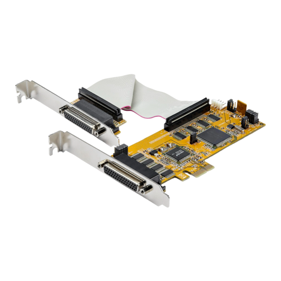
8-Port PCI Express Low Profile RS232 Serial Card | 16C1050 UART
Product Diagram (PEX8S1050LP)
1
2
3
Component
S5 - S8: DB44 Pin
• Used to connect the DB44 to 4-Port DB9
1
Connector to 4-Port
Breakout Cable.
Breakout Cable
• Used to set pin 9 on the DB9 connector (S1 -
S4) to RI (no power) or to DC power. The JP2
JP 5 - Power Over
Aux Power Source Selector determines the
2
Serial Connector
voltage 12 or 5.
• Default position is RI.
S1 - S4: DB44 Pin
• Used to connect the DB44 to 4-Port DB9
3
Connector to 4-Port
Breakout Cable.
Breakout Cable
• Used to connect the PCI Express Card to
4
PCI Express Connector
the PCI Express expansion slot on the Host
Computer.
To view manuals, FAQs, videos, drivers, downloads, technical drawings, and more, visit www.startech.com/support.
9
8
7
6
5
4
Function
• Used to enable or disable the wake from sleep
5
setting.
JP1: PME
• Default position is disable.
• Used for factory testing.
6
JP4: Mode
• For normal use the jumper must be set to CEN.
JP6: S5 - S8
• Used to enable or disable power over serial for
7
Power Over Serial
S5 - S8 connectors.
Connectors
• Used to select the DC power source for Pin 9 on
the DB9 connector.
• Internal 12V: Power supplied by
JP2: AUX Power
motherboard's PCI Express Slot.
8
Source Selector
• External 12V: Power supplied by J3 Power
Connector.
• External 5V: Power supplied by J3 Power
Connector.
J3 Aux. Power
• Used to connect an external power source to
9
Connector
the Serial Card.
Requirements
For the latest requirements, please visit
Installation
WARNING! PCI Express cards can be severely damaged by static electricity. Be sure
that you are properly grounded before touching the Serial Card.
1. Turn Off the Host Computer.
2. Remove the chassis cover from the Host Computer.
3. Locate a PCI Express Slot, using a Screwdriver (sold separately) remove the Screw
used to secure the PCI Express Slot Cover and set the Screw aside.
4. Align the PCI Express Connector on the Serial Card with a PCI Express Slot. While
applying pressure evenly across the top edge of the Serial Card, insert the Serial
Card into the PCI Express Slot, ensuring that the Serial Card is properly aligned
with the rear panel slot.
5. Using a Screwdriver and the Screw removed in step 3, secure the Serial Card to
the motherboard and rear chassis. Secure the additional serial port provided by the
daughter board (smaller circuit board) to an adjacent rear bracket.
Quick-Start Guide
www.startech.com/PEX8S1050LP
Manual Revision: August 16, 2019 9:03 AM
Advertisement

Subscribe to Our Youtube Channel
Related Manuals for StarTech.com PEX8S1050LP


Summary of Contents for StarTech.com PEX8S1050LP
- Page 1 Secure the additional serial port provided by the daughter board (smaller circuit board) to an adjacent rear bracket. To view manuals, FAQs, videos, drivers, downloads, technical drawings, and more, visit www.startech.com/support. Manual Revision: August 16, 2019 9:03 AM...
- Page 2 London, Ontario Parkwy Gowerton Rd, and do not represent an endorsement of a product or service by StarTech.com, or an endorsement of the product(s) to which NL: startech.com/nl Brackmills this manual applies by the third-party company in question. StarTech.com hereby acknowledges that all trademarks, registered...
Need help?
Do you have a question about the PEX8S1050LP and is the answer not in the manual?
Questions and answers