Table of Contents
Advertisement
Quick Links
ASSEMBLY AND INSTALLATION
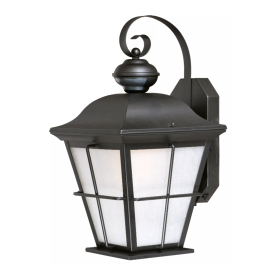
T0246 / T0247
WARNING:
NOTES: 1. Before installing, consult local electrical codes for wiring and grounding requirements.
2. Read and save these instructions.
Important to Know
1. Read all instructions carefully before installation and
operation.
2. If you are not familiar with state and local electrical
codes, it is recommended that you consult with a
qualified electrician.
3. Before installation, shut off power at the main fuse or
circuit breaker box. Be aware that simply turning off
the wall switch is not sufficient to prevent an electrical
shock.
4. This fixture requires a 120 VAC, 60 Hz power source.
Maximum wattage light bulb is 60W.
5. Do not attempt to take the lantern apart; there are
no serviceable parts inside.
6. To avoid sensor damage by lightning or electrical
surge, make sure the grounding wire is securely
connected.
7. For general safety and to avoid any possible damage
to the sensor, be sure the power is switched "off"
before replacing the bulb.
Maximum Wattage: 60W
Work Temperature: -4
Hardware Package (included)
Mounting Plate
Headless Screw
X1
X2
INSTRUCTIONS
TO AVOID RISK OF ELECTRICAL SHOCK, BE SURE TO SHUT OFF
POWER BEFORE INSTALLING OR SERVICING THIS FIXTURE.
0
0
F ~ 104
F
Wire Nut
Rubber Pad
X3
X2
Features
1. Energy saving fixture.
2. Use the dim-to-bright illumination option where
you want some minimum illumination through out
the night, such as at your front entrance or garage
door. Use the dark-to-bright illumination option
where you do not need minimum brightness, such
as the backyard or back porch.
3.When in manual override mode, use wall switch
to keep the light on till dawn.
Mounting Screw
X2
Page 1 / 5
Lock Nut (D)
Ball Nut
X2
X4
Green Grounding
Screw
160929
Advertisement
Table of Contents

Subscribe to Our Youtube Channel
Summary of Contents for Vaxcel T0246
- Page 1 ASSEMBLY AND INSTALLATION INSTRUCTIONS T0246 / T0247 WARNING: TO AVOID RISK OF ELECTRICAL SHOCK, BE SURE TO SHUT OFF POWER BEFORE INSTALLING OR SERVICING THIS FIXTURE. NOTES: 1. Before installing, consult local electrical codes for wiring and grounding requirements. 2. Read and save these instructions.
- Page 2 Bolt Nuts Rubber Pad Headless Screw Mounting plate Lens Lock Nut Fixture Wire Small Bolt Nuts Outlet Box Small Rubber Pads Fixture Glass Panels Green Grounding Screw Wire Nut Max.60W type A House Grounding Wire Back Plate standard base bulb Fixture Grounding Wire Studs (Bulb not included)
- Page 3 Turn on the power at fuse or circuit box. Function and Operation MODES OF OPERATION Choose a mode by sliding the switch on the bottom of the back plate of the fixture. (See Fig.3 ). When power is first applied, the light will turn to high level brightness, wait for 15 seconds to allow the sensor to warm up. 1.
- Page 4 Fig.3 CUSTOMIZATION OPTIONS: (View from Bottom of Back plate) Shut-off Delay The Shut-off delay is the length of time the light will stay at high- level brightness after motion has ceased to be detected. This Shut-off delay can be set when operation is in 3, 6 or 0 Mode by TIME TEST SENSITIVITY...
- Page 5 2. Make sure of using incandescent bulb or dimmable LED bulb. The following parts are available for re-order if damaged or missing. Spare Parts List: Glass Panel Assembly Kit 9839FE for T0246 5533MM(1 SET) 9840FE for T0247 Headless Screw Rubber Pad...


Need help?
Do you have a question about the T0246 and is the answer not in the manual?
Questions and answers