Table of Contents
Advertisement
Quick Links
www.ti.com
User's Guide
TPS65253 Buck Converter Evaluation Module User's
Guide
1
Introduction.............................................................................................................................................................................2
2
Background.............................................................................................................................................................................3
3
Schematic................................................................................................................................................................................4
4
Placement................................................................................................................................................................................5
5 Bench Test Setup Conditions................................................................................................................................................
5.2
Jumpers..............................................................................................................................................................................9
Placement.................................................................................................................................................9
6 Power-Up Procedure............................................................................................................................................................
Materials......................................................................................................................................................................11
8 Revision History...................................................................................................................................................................
Trademarks
All trademarks are the property of their respective owners.
SLVU469B - JUNE 2011 - REVISED MAY 2021
Submit Document Feedback
Table of Contents
Placement.....................................................................................................................8
Copyright © 2021 Texas Instruments Incorporated
TPS65253 Buck Converter Evaluation Module User's Guide
Table of Contents
8
10
12
1
Advertisement
Table of Contents

Related Manuals for Texas Instruments TPS65253


Summary of Contents for Texas Instruments TPS65253
-
Page 1: Table Of Contents
7 Bill of Materials..................................11 8 Revision History................................... Trademarks All trademarks are the property of their respective owners. SLVU469B – JUNE 2011 – REVISED MAY 2021 TPS65253 Buck Converter Evaluation Module User's Guide Submit Document Feedback Copyright © 2021 Texas Instruments Incorporated... -
Page 2: Introduction
Introduction www.ti.com 1 Introduction This document presents the information required to power the TPS65253 PMIC as well as the support documentation including schematic and bill of materials. TPS65253 Buck Converter Evaluation Module User's Guide SLVU469B – JUNE 2011 – REVISED MAY 2021 Submit Document Feedback Copyright ©... -
Page 3: Background
2 Background The TPS65253 PMIC is designed to provide 3.5-A and 2.5-A continuous outputs with an operational range of 4.5 V to 16 V and an externally set switching frequency ranging from 300 kHz to 1.2 MHz. When the PMIC is not fully loaded, buck1 can be loaded to 4 A and buck 2 to 3 A. -
Page 4: Schematic
3 Schematic Figure 3-1 illustrates the TPS65253 EVM schematic. The resistor and capacitor values have been chosen according to the guidelines presented on the TPS65253 spec available at http://focus.ti.com/docs/ prod/folders/print/TPS65253.html. Note that for the purpose of gains-phase measurements R9 and R11 (0 Ω on the EVM) need to be replaced by suitable low value resistors as per the network analyzer setup required. -
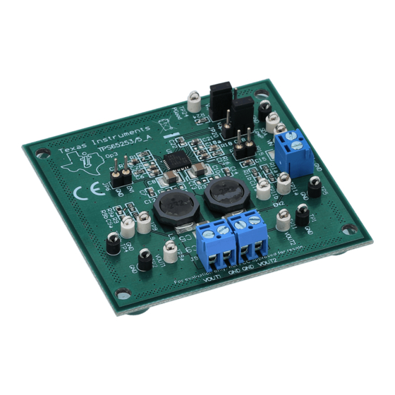
Page 5: Placement
Placement 4 Placement Figure 4-1. Part Placement Figure 4-2. Top Layer SLVU469B – JUNE 2011 – REVISED MAY 2021 TPS65253 Buck Converter Evaluation Module User's Guide Submit Document Feedback Copyright © 2021 Texas Instruments Incorporated... - Page 6 Placement www.ti.com Figure 4-3. Mid-Layer 1 Figure 4-4. Mid-Layer 2 TPS65253 Buck Converter Evaluation Module User's Guide SLVU469B – JUNE 2011 – REVISED MAY 2021 Submit Document Feedback Copyright © 2021 Texas Instruments Incorporated...
- Page 7 Placement Figure 4-5. Bottom Layer SLVU469B – JUNE 2011 – REVISED MAY 2021 TPS65253 Buck Converter Evaluation Module User's Guide Submit Document Feedback Copyright © 2021 Texas Instruments Incorporated...
-
Page 8: Bench Test Setup Conditions
Black – GND White – Each output, feed-back, power good and V . All marking on PCB. TPS65253 Buck Converter Evaluation Module User's Guide SLVU469B – JUNE 2011 – REVISED MAY 2021 Submit Document Feedback Copyright © 2021 Texas Instruments Incorporated... -
Page 9: Jumpers
Low_P Low Power input White Power Good TP24 PGOOD White (open drain connected to Buck1 output) SLVU469B – JUNE 2011 – REVISED MAY 2021 TPS65253 Buck Converter Evaluation Module User's Guide Submit Document Feedback Copyright © 2021 Texas Instruments Incorporated... -
Page 10: Power-Up Procedure
100 ms. PGOOD will be asserted high 32 ms after all converter outputs have reached 90% of nominal voltages. 4. Apply loads to the output connectors (J9 and J11). TPS65253 Buck Converter Evaluation Module User's Guide SLVU469B – JUNE 2011 – REVISED MAY 2021 Submit Document Feedback... -
Page 11: Bill Of Materials
C4, C6, C15, CAP 4700 pF 50 V 4.7 nF Panasonic-ECG ECJ-1VB1H472K PCC1780TR-ND C17, C18 CERAMIC X7R 0603 SLVU469B – JUNE 2011 – REVISED MAY 2021 TPS65253 Buck Converter Evaluation Module User's Guide Submit Document Feedback Copyright © 2021 Texas Instruments Incorporated... -
Page 12: Revision History
Changes from Revision * (June 2011) to Revision A (November 2015) Page • Updated schematic image..........................TPS65253 Buck Converter Evaluation Module User's Guide SLVU469B – JUNE 2011 – REVISED MAY 2021 Submit Document Feedback Copyright © 2021 Texas Instruments Incorporated... - Page 13 STANDARD TERMS FOR EVALUATION MODULES Delivery: TI delivers TI evaluation boards, kits, or modules, including any accompanying demonstration software, components, and/or documentation which may be provided together or separately (collectively, an “EVM” or “EVMs”) to the User (“User”) in accordance with the terms set forth herein.
- Page 14 www.ti.com Regulatory Notices: 3.1 United States 3.1.1 Notice applicable to EVMs not FCC-Approved: FCC NOTICE: This kit is designed to allow product developers to evaluate electronic components, circuitry, or software associated with the kit to determine whether to incorporate such items in a finished product and software developers to write software applications for use with the end product.
- Page 15 www.ti.com Concernant les EVMs avec antennes détachables Conformément à la réglementation d'Industrie Canada, le présent émetteur radio peut fonctionner avec une antenne d'un type et d'un gain maximal (ou inférieur) approuvé pour l'émetteur par Industrie Canada. Dans le but de réduire les risques de brouillage radioélectrique à...
- Page 16 www.ti.com EVM Use Restrictions and Warnings: 4.1 EVMS ARE NOT FOR USE IN FUNCTIONAL SAFETY AND/OR SAFETY CRITICAL EVALUATIONS, INCLUDING BUT NOT LIMITED TO EVALUATIONS OF LIFE SUPPORT APPLICATIONS. 4.2 User must read and apply the user guide and other available documentation provided by TI regarding the EVM prior to handling or using the EVM, including without limitation any warning or restriction notices.
- Page 17 Notwithstanding the foregoing, any judgment may be enforced in any United States or foreign court, and TI may seek injunctive relief in any United States or foreign court. Mailing Address: Texas Instruments, Post Office Box 655303, Dallas, Texas 75265 Copyright © 2019, Texas Instruments Incorporated...
- Page 18 TI products. TI’s provision of these resources does not expand or otherwise alter TI’s applicable warranties or warranty disclaimers for TI products.IMPORTANT NOTICE Mailing Address: Texas Instruments, Post Office Box 655303, Dallas, Texas 75265 Copyright © 2021, Texas Instruments Incorporated...
Need help?
Do you have a question about the TPS65253 and is the answer not in the manual?
Questions and answers