Table of Contents
Advertisement
Quick Links
Advertisement
Table of Contents

Related Manuals for Texas Instruments TPS61177AEVM


Summary of Contents for Texas Instruments TPS61177AEVM
- Page 1 TPS61177AEVM User Guide User's Guide Literature Number: SNVU490 OCTOBER 2015...
-
Page 2: Table Of Contents
Overvoltage Protection ..................6.5.5 Undervoltage Lockout ....................... ID Register ....................EEPROM Default Values ................Instructions for Programming EEPROM ..............Related Documentation From Texas Instruments Table of Contents SNVU490 – OCTOBER 2015 Submit Documentation Feedback Copyright © 2015, Texas Instruments Incorporated... - Page 3 List of Figures ..................TPS61177AEVM Evaluation Board ..............TPS61177AEVM With USB2Any Board Connected ..................... TPS61177A GUI - First Page ..................Option to Select Register Control ................TPS61177A GUI - Register Control Page ..................... Default Jumper Configuration ............. TPS61177A EVM Test Setup for Standalone Evaluation ........
-
Page 4: Introduction
Introduction The Texas Instruments TPS61177AEVM evaluation module (EVM) helps designers evaluate the operation and performance of the TPS61177A High-Efficiency LED Backlight Driver. The device offers configurability and can be set up to switch at 450 kHz, 600 kHz, 800 kHz, and 1.2 MHz. - Page 5 TP12 - Test Point: This header is test point for CS1(LED driver out for channel 1). TP13 - Test Point: This header is test point for CS6(LED driver out for channel 6). SNVU490 – OCTOBER 2015 List of Tables Submit Documentation Feedback Copyright © 2015, Texas Instruments Incorporated...
-
Page 6: Tps61177Aevm Set-Up
TPS61177AEVM Set-Up Figure 2. TPS61177AEVM With USB2Any Board Connected External power must be provided to the board. A standard USB to mini USB cable must be connected to the USB2ANY from a PC. The I2C-compatible interface program provides all of the controls that the TPS61177A device requires. - Page 7 Set-Up www.ti.com • Click "Next" button. • Check to accept the agreement and click “Next” button to proceed with installation. SNVU490 – OCTOBER 2015 List of Tables Submit Documentation Feedback Copyright © 2015, Texas Instruments Incorporated...
- Page 8 • Click “Next” button. In default, program will be installed in C:\Program Files (x86)\Texas Instruments\TPS61177A folder and Texas Instruments\TPS61177AEVM in start menu. • Check to create a desktop icon for the program and click “Next” button. List of Tables SNVU490 –...
- Page 9 Set-Up www.ti.com • Click “Install” button. • Click “Finish” button to finish installation and launch the program. SNVU490 – OCTOBER 2015 List of Tables Submit Documentation Feedback Copyright © 2015, Texas Instruments Incorporated...
- Page 10 If firmware update of USB2ANY adaptor is needed this window will pop up. • Depending on firmware versions in USB2ANY adaptors, this firmware uploader will appear, and then follow the instruction on this window. List of Tables SNVU490 – OCTOBER 2015 Submit Documentation Feedback Copyright © 2015, Texas Instruments Incorporated...
- Page 11 After disconnecting USB cable and plugging it while pressing S1 button, this window will pop up and it is ready to be updated. Press “Update Firmware” button. SNVU490 – OCTOBER 2015 List of Tables Submit Documentation Feedback Copyright © 2015, Texas Instruments Incorporated...
- Page 12 Set-Up www.ti.com • Update is finished. List of Tables SNVU490 – OCTOBER 2015 Submit Documentation Feedback Copyright © 2015, Texas Instruments Incorporated...
- Page 13 PC and “Connected” will change to “Not connected”. The first screen of the GUI will show the brief information and connecting diagram of the device (see Figure SNVU490 – OCTOBER 2015 List of Tables Submit Documentation Feedback Copyright © 2015, Texas Instruments Incorporated...
-
Page 14: Tps61177A Gui
Figure 3. TPS61177A GUI - First Page In order to control registers of the device, click the icon on the upper left corner, and select “Registers” page option. List of Tables SNVU490 – OCTOBER 2015 Submit Documentation Feedback Copyright © 2015, Texas Instruments Incorporated... - Page 15 Set-Up www.ti.com Figure 4. Option to Select Register Control This is the register control window selected by the page option. SNVU490 – OCTOBER 2015 List of Tables Submit Documentation Feedback Copyright © 2015, Texas Instruments Incorporated...
-
Page 16: Tps61177A Gui - Register Control Page
“Enable I2C Pullup” is used to enable internal pullup (3.3 V) of USB2ANY when I2C pullup on TPS61177AEVM is not available. I2C clock speed can be also selected from 1 0kHz to 400 kHz and default speed is set to 100 kHz. EN signal from USB2ANY can be inserted by checking “Enable Pin”... - Page 17 Register settings can be saved to “”*.json” file format by selecting “Save Registers” from file menu. Register settings saved as “*.json” file format can be opened and programmed automatically by selecting “Load Register” from file menu. SNVU490 – OCTOBER 2015 List of Tables Submit Documentation Feedback Copyright © 2015, Texas Instruments Incorporated...
-
Page 18: Instructions Fo Stand-Alone Evaluation
Figure 7 shows the picture of the TPS61177A EVM board setup for the standalone evaluation (LED load: WLEDEVM-260, not included in the kit). List of Tables SNVU490 – OCTOBER 2015 Submit Documentation Feedback Copyright © 2015, Texas Instruments Incorporated... -
Page 19: Instructions For Evaluation With Software
Contained in this document is a description of how to use the USB2ANY board with the evaluation board and the interface software. Figure 8 shows the picture of the TPS61177AEVM setup for the evaluation with software. SNVU490 – OCTOBER 2015 List of Tables Submit Documentation Feedback... -
Page 20: Tps61177Aevm Component Placement
Figure 8. TPS61177A EVM Test Setup With USB2ANY Connected for Software Control The USB2ANY Board can be connected to the TPS61177AEVM via J8 connector. The USB2ANY Board provides all of the control signals for the simple interface. Power to the part must be provided externally. A standard USB cable must be connected to the USB2ANY board from a PC. -
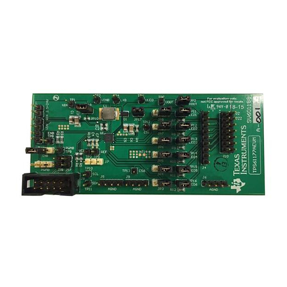
Page 21: Tps61177Aevm Component Placement (Layout)
TPS61177AEVM Component Placement www.ti.com Figure 9. TPS61177AEVM Component Placement (Layout) SNVU490 – OCTOBER 2015 List of Tables Submit Documentation Feedback Copyright © 2015, Texas Instruments Incorporated... -
Page 22: Schematic
Schematic www.ti.com Schematic Figure 10. TPS61177AEVM Schematic List of Tables SNVU490 – OCTOBER 2015 Submit Documentation Feedback Copyright © 2015, Texas Instruments Incorporated... -
Page 23: Tps61177Aevm Bill Of Materials
W x 0.200 inches H - 10,000 per roll RGR0020A TPS61177ARGRR TPS61177ARGRR WLED Driver for Notebooks with PWM Interface and Mixed Dimming Mode, RGR0020A SNVU490 – OCTOBER 2015 List of Tables Submit Documentation Feedback Copyright © 2015, Texas Instruments Incorporated... -
Page 24: Tps61177A Usage And Programming
The default value of CS bits is 101b setting 20 mA. 6.4.2 PWM Output Frequency PWM output freq on direct PWM mode and mixed dimming mode is determined by input PWM frequency. List of Tables SNVU490 – OCTOBER 2015 Submit Documentation Feedback Copyright © 2015, Texas Instruments Incorporated... -
Page 25: Dimming Mode Settings
The device slave register of TPS61177A is 58h in 8-bit (7bit slave address + R/W bit) or 2Ch in 7-bit without R/W bit. EEPROM Default Values Refer to TPS61177A data sheet (SNVSA76) for detailed descriptions. SNVU490 – OCTOBER 2015 List of Tables Submit Documentation Feedback Copyright © 2015, Texas Instruments Incorporated... -
Page 26: Instructions For Programming Eeprom
Writing 80h to register addr FFh will write EEPROM with updated values or check “WED bit” checkbox of the GUI. Related Documentation From Texas Instruments See the TPS61177A data sheet (SNVSA76) for more information. List of Tables SNVU490 – OCTOBER 2015 Submit Documentation Feedback Copyright © 2015, Texas Instruments Incorporated... - Page 27 IMPORTANT NOTICE Texas Instruments Incorporated and its subsidiaries (TI) reserve the right to make corrections, enhancements, improvements and other changes to its semiconductor products and services per JESD46, latest issue, and to discontinue any product or service per JESD48, latest issue.
- Page 28 Mouser Electronics Authorized Distributor Click to View Pricing, Inventory, Delivery & Lifecycle Information: Texas Instruments TPS61177AEVM...
Need help?
Do you have a question about the TPS61177AEVM and is the answer not in the manual?
Questions and answers