Advertisement
Quick Links
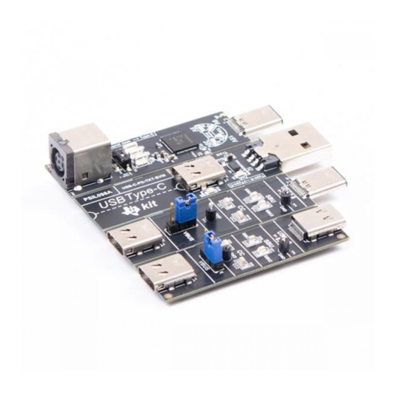
This user's guide describes the TPS65987DDJ evaluation module (USB-C-PD-TKT-EVM). The USB-C-
PD-TKT-EVM allows for the evaluation of the TPS65987DDJ Power Delivery (PD). In addition, the EVM
contains a Type-A to USB Type-C converter, a plug-to-receptacle converter, and a passing through board
for debugging purposes. The USB-C-PD-TKT-EVM uses default configurations to allow for sourcing 45 W
or 60 W by simply using a switch. This document contains an introduction, setup conditions, the EVM
schematics, top- and bottom-board layouts and component views, layout, and a bill of materials (BOM).
Figure 1. Front Layout
Trademarks
USB Type-C is a trademark of USB Implementers Forum.
All other trademarks are the property of their respective owners.
1
Introduction
The USB-C-PD-TKT-EVM allows the TPS65987DDJ device to enter default configuration 2 which supports
a 45-W source and default configuration 4 which supports a 60-W source. The USB-C-PD-TKT-EVM
contains a Type-A to USB Type-C converter, a plug-to-receptacle converter, and a passing through board
for debugging purposes.
2
Setup and Switches, Test Points, and LED Descriptions
2.1
LEDs (D1), (D3), (D7), and (D8)
These LEDs highlight if the source board is outputting a 5-V, 9-V, 15-V, or 20-V PD contract respectively.
SLVUBQ7 – August 2019
Submit Documentation Feedback
USB Type-C™ PD TKT Evaluation Module
Copyright © 2019, Texas Instruments Incorporated
User's Guide
SLVUBQ7 – August 2019
Figure 2. Back Layout
USB Type-C™ PD TKT Evaluation Module
1
Advertisement

Related Manuals for Texas Instruments USB-C-PD-TKT-EVM


Summary of Contents for Texas Instruments USB-C-PD-TKT-EVM
- Page 1 Type-A to USB Type-C converter, a plug-to-receptacle converter, and a passing through board for debugging purposes. The USB-C-PD-TKT-EVM uses default configurations to allow for sourcing 45 W or 60 W by simply using a switch. This document contains an introduction, setup conditions, the EVM schematics, top- and bottom-board layouts and component views, layout, and a bill of materials (BOM).
- Page 2 Use this set of tests points for I2C communication in case of user-defined configurations from an SPI flash. TP13, TP14, and TP15 connect to the I2C1_SCL, I2C1_SDA, and the ground nets, respectively. USB Type-C™ PD TKT Evaluation Module SLVUBQ7 – August 2019 Submit Documentation Feedback Copyright © 2019, Texas Instruments Incorporated...
- Page 3 Figure 3 through Figure 9 illustrate the USB-C-PD-TKT-EVM schematics. Figure 3. DC/DC Buck Converter Figure 4. PD Controller Figure 5. Power Path SLVUBQ7 – August 2019 USB Type-C™ PD TKT Evaluation Module Submit Documentation Feedback Copyright © 2019, Texas Instruments Incorporated...
- Page 4 USB-C-PD-TKT-EVM Schematics www.ti.com Figure 6. LED Control USB Type-C™ PD TKT Evaluation Module SLVUBQ7 – August 2019 Submit Documentation Feedback Copyright © 2019, Texas Instruments Incorporated...
- Page 5 USB-C-PD-TKT-EVM Schematics www.ti.com Figure 7. Type-A to USB Type-C™ Converter SLVUBQ7 – August 2019 USB Type-C™ PD TKT Evaluation Module Submit Documentation Feedback Copyright © 2019, Texas Instruments Incorporated...
- Page 6 USB-C-PD-TKT-EVM Schematics www.ti.com Figure 8. Plug to Receptacle Figure 9. Receptacle to Receptacle USB Type-C™ PD TKT Evaluation Module SLVUBQ7 – August 2019 Submit Documentation Feedback Copyright © 2019, Texas Instruments Incorporated...
- Page 7 USB-C-PD-TKT-EVM Board Layout Figure 10 through Figure 21 show the USB-C-PD-TKT-EVM PCB layout images. Figure 10. USB-C-PD-TKT-EVM Top Overlay Figure 11. USB-C-PD-TKT-EVM Top Solder Figure 12. USB-C-PD-TKT-EVM Top Layer Figure 13. USB-C-PD-TKT-EVM GND Plane 1 Figure 14. USB-C-PD-TKT-EVM High Speed Figure 15.
- Page 8 USB-C-PD-TKT-EVM Board Layout www.ti.com Figure 16. USB-C-PD-TKT-EVM Power 1 Figure 17. USB-C-PD-TKT-EVM Power 2 Figure 18. USB-C-PD-TKT-EVM Plane 3 Figure 19. USB-C-PD-TKT-EVM Bottom Layer Figure 20. USB-C-PD-TKT-EVM Bottom Solder Figure 21. USB-C-PD-TKT-EVM Bottom Overlay USB Type-C™ PD TKT Evaluation Module SLVUBQ7 –...
- Page 9 22 Position, R/A, SMT Unless otherwise noted in the Alternate Part Number or Alternate Manufacturer columns, all parts may be substituted with equivalents. SLVUBQ7 – August 2019 USB Type-C™ PD TKT Evaluation Module Submit Documentation Feedback Copyright © 2019, Texas Instruments Incorporated...
- Page 10 RES, 36.5 kΩ, 1%, 0.063 W, AEC-Q200 Grade 0, 0402 CRCW040236K5FKED Vishay-Dale 0402 60.4 kΩ RES, 60.4 kΩ, 1%, 0.063 W, AEC-Q200 Grade 0, 0402 CRCW040260K4FKED Vishay-Dale 0402 USB Type-C™ PD TKT Evaluation Module SLVUBQ7 – August 2019 Submit Documentation Feedback Copyright © 2019, Texas Instruments Incorporated...
- Page 11 Regulator, DBZ0003A (SOT-23-3) Instruments SPST USB 2.0 High-Speed Switch With Battery RSE0010A BQ24392RSER Texas Texas Instruments Charging Detection, RSE0010A (UQFN-10) Instruments SLVUBQ7 – August 2019 USB Type-C™ PD TKT Evaluation Module Submit Documentation Feedback Copyright © 2019, Texas Instruments Incorporated...
- Page 12 RES, 0, 5%, 0.1 W, 0603 0603 RC0603JR-070RL Yageo RES, 0, 5%, 0.125 W, AEC-Q200 Grade 0, 0805 0805 ERJ-6GEY0R00V Panasonic USB Type-C™ PD TKT Evaluation Module SLVUBQ7 – August 2019 Submit Documentation Feedback Copyright © 2019, Texas Instruments Incorporated...
- Page 13 STANDARD TERMS FOR EVALUATION MODULES Delivery: TI delivers TI evaluation boards, kits, or modules, including any accompanying demonstration software, components, and/or documentation which may be provided together or separately (collectively, an “EVM” or “EVMs”) to the User (“User”) in accordance with the terms set forth herein.
- Page 14 www.ti.com Regulatory Notices: 3.1 United States 3.1.1 Notice applicable to EVMs not FCC-Approved: FCC NOTICE: This kit is designed to allow product developers to evaluate electronic components, circuitry, or software associated with the kit to determine whether to incorporate such items in a finished product and software developers to write software applications for use with the end product.
- Page 15 www.ti.com Concernant les EVMs avec antennes détachables Conformément à la réglementation d'Industrie Canada, le présent émetteur radio peut fonctionner avec une antenne d'un type et d'un gain maximal (ou inférieur) approuvé pour l'émetteur par Industrie Canada. Dans le but de réduire les risques de brouillage radioélectrique à...
- Page 16 www.ti.com EVM Use Restrictions and Warnings: 4.1 EVMS ARE NOT FOR USE IN FUNCTIONAL SAFETY AND/OR SAFETY CRITICAL EVALUATIONS, INCLUDING BUT NOT LIMITED TO EVALUATIONS OF LIFE SUPPORT APPLICATIONS. 4.2 User must read and apply the user guide and other available documentation provided by TI regarding the EVM prior to handling or using the EVM, including without limitation any warning or restriction notices.
- Page 17 Notwithstanding the foregoing, any judgment may be enforced in any United States or foreign court, and TI may seek injunctive relief in any United States or foreign court. Mailing Address: Texas Instruments, Post Office Box 655303, Dallas, Texas 75265 Copyright © 2019, Texas Instruments Incorporated...
- Page 18 TI products. TI’s provision of these resources does not expand or otherwise alter TI’s applicable warranties or warranty disclaimers for TI products. Mailing Address: Texas Instruments, Post Office Box 655303, Dallas, Texas 75265 Copyright © 2019, Texas Instruments Incorporated...
Need help?
Do you have a question about the USB-C-PD-TKT-EVM and is the answer not in the manual?
Questions and answers