Table of Contents
Advertisement
Quick Links
Advertisement
Table of Contents

Subscribe to Our Youtube Channel
Related Manuals for Supermicro A+ SERVER 1022G-URF


Summary of Contents for Supermicro A+ SERVER 1022G-URF
- Page 1 UPER ® A+ SERVER 1022G-URF USER’S MANUAL Revision1.0e...
- Page 2 This product, including software and documentation, is the property of Supermicro and/or its licensors, and is supplied only under a license. Any use or reproduction of this product is not allowed, except as expressly permitted by the terms of said license.
- Page 3 About This Manual This manual is written for professional system integrators and PC technicians. It provides information for the installation and use of the A+ SERVER 1022G-URF. Installation and maintenance should be performed by experienced technicians only. The A+ SERVER 1022G-URF is a 1U rackmount server based on the SC815TQ-R700UB server chassis and the Super H8DGU-F serverboard.
- Page 4 A+ Server 1022G-URF User's Guide Chapter 5: Advanced Serverboard Setup This chapter provides detailed information on the H8DGU-F serverboard, including the locations and functions of connectors, headers and jumpers. Refer to this chap- ter when adding or removing processors or main memory and when reconfiguring the serverboard.
-
Page 5: Table Of Contents
SATA Subsystem ..................... 1-3 PCI Expansion Slots ..................1-3 Front Control Panel ..................1-3 I/O Backplane ....................1-4 Cooling System ....................1-4 Contacting Supermicro ..................1-6 Chapter 2 Server Installation Overview ......................2-1 Unpacking the System ..................2-1 Preparing for Setup ..................2-1 Choosing a Setup Location ................ - Page 6 A+ Server 1022G-URF User's Guide Installing the System into a Rack ..............2-4 Identifying the Sections of the Rack Rails ............2-4 Installing the Outer Rails ................. 2-5 Installing the Server into the Rack ..............2-6 Installing the Server into a Telco Rack ............2-7 Checking the Serverboard Setup ..............
- Page 7 Preface Chapter 5 Advanced Serverboard Setup Handling the Serverboard ................5-1 Precautions ..................... 5-1 Unpacking ....................... 5-1 Processor and Heatsink Installation..............5-2 Installing a Passive CPU Heatsink ..............5-4 Connecting Cables ..................5-5 Connecting Data Cables ................. 5-5 Connecting Power Cables ................5-5 Connecting the Control Panel .................
- Page 8 A+ Server 1022G-URF User's Guide System Fans ....................6-2 System Fan Failure ..................6-3 Drive Bay Installation/Removal ............... 6-4 Removing the Front Bezel ................6-4 Accessing the Drive Bays ................6-4 Hard Drive Installation ..................6-5 DVD-ROM Drive Installation ................6-6 Power Supply ....................
-
Page 9: Chapter 1 Introduction
Chapter 1 Introduction Overview The A+ Server 1022G-URF is a high-end server comprised of two main subsys- tems: the SC815TQ-R700UB 1U server chassis and the H8DGU-F dual processor serverboard. Please refer to our web site for information on operating systems that have been certified for use with the system (www.supermicro.com). -
Page 10: Serverboard Features
Serverboard Features At the heart of the A+ SERVER 1022G-URF lies the H8DGU-F, a dual processor serverboard based on the AMD SR5670/SP5100 chipset. Below are the main fea- tures of the H8DGU-F. (See Figure 1-1 for a block diagram of the chipset). -
Page 11: Onboard Controllers/Ports
Chapter 1: Introduction Note: You must have RAID set up to enable the hot-swap capability of the SATA drives. Documentation on RAID setup guidelines can be found on our web site. Onboard Controllers/Ports The color-coded I/O ports include two COM ports (one header and one port), a VGA (monitor) port, Seven USB 2.0 ports (2x rear, 4x header, 1x type A), PS/2 mouse and keyboard ports, two gigabit Ethernet ports and one dedicated IPMI LAN port. -
Page 12: Pci Expansion Slots
+ SE VER 1022G-URF User's Manual PCI Expansion Slots A riser card (RSC-R1UU-UE16, optional) on the right side of the chassis can sup- port an AOC-PG-i2+ add-on card to provide two additional Gb LAN ports. The left side supports a UIO card and one PCI-E x16 card. Front Control Panel The chassis control panel provides you with system monitoring and control. - Page 13 Chapter 1: Introduction Figure 1-1. AMD SR5670/SP5100 Chipset: System Block Diagram Note: This is a general block diagram. Please see Chapter 5 for details. DIMM A1 HT3 Link DIMM A1 DIMM A0 16x16-3.2GT/s DIMM A0 DIMM B1 DIMM B1 DIMM B0 HT3 Link Socket G34 Socket G34...
-
Page 14: Contacting Supermicro
Super Micro Computer, Inc. 980 Rock Ave. San Jose, CA 95131 U.S.A. Tel: +1 (408) 503-8000 Fax: +1 (408) 503-8008 Email: marketing@supermicro.com (General Information) support@supermicro.com (Technical Support) Web Site: www.supermicro.com Europe Address: Super Micro Computer B.V. Het Sterrenbeeld 28, 5215 ML... -
Page 15: Chapter 2 Server Installation
Unpacking the System You should inspect the box the A+ SERVER 1022G-URF was shipped in and note if it was damaged in any way. If the server itself shows damage you should file a damage claim with the carrier who delivered it. -
Page 16: Warnings And Precautions
ERVER 1022G-URF User's Manual installation only in a Restricted Access Location (dedicated equipment rooms, service closets and the like). • This product is not suitable for use with visual display work place devices acccording to §2 of the the German Ordinance for Work with Visual Display Units. -
Page 17: Rack Mounting Considerations
Chapter 2: Server Installation Rack Mounting Considerations Ambient Operating Temperature If installed in a closed or multi-unit rack assembly, the ambient operating temperature of the rack environment may be greater than the ambient temperature of the room. Therefore, consideration should be given to installing the equipment in an environment compatible with the manufacturer’s maximum rated ambient temperature (Tmra). -
Page 18: Installing The System Into A Rack
ERVER 1022G-URF User's Manual Installing the System into a Rack This section provides information on installing the 1022G-URF into a rack unit with the rack rails provided. If the system has already been mounted into a rack, you can skip ahead to Sections 2-6 and 2-7. There are a variety of rack units on the market, which may mean the assembly procedure will differ slightly. -
Page 19: Installing The Outer Rails
Chapter 2: Server Installation Installing the Outer Rails Begin by measuring the distance from the front rail to the rear rail of the rack. Attach a short bracket to the front side of the right outer rail and a long bracket to the rear side of the right outer rail. -
Page 20: Installing The Server Into The Rack
ERVER 1022G-URF User's Manual Installing the Server into the Rack You should now have rails attached to both the chassis and the rack unit. The next step is to install the server into the rack. Do this by lining up the rear of the chassis rails with the front of the rack rails. -
Page 21: Installing The Server Into A Telco Rack
Chapter 2: Server Installation Installing the Server into a Telco Rack To install the 1022G-URF into a Telco type rack, use two L-shaped brackets on either side of the chassis (four total). First, determine how far follow the server will extend out the front of the rack. -
Page 22: Checking The Serverboard Setup
ERVER 1022G-URF User's Manual Checking the Serverboard Setup After you install the 1022G-URF in the rack, you will need to open the top cover to make sure the serverboard is properly installed and all the connections have been made. Accessing the Inside of the System 1. -
Page 23: Checking The Drive Bay Setup
Chapter 2: Server Installation Figure 2-5. Accessing the Inside of the System Checking the Drive Bay Setup Next, you should check to make sure the peripheral drives and the SATA drives and SATA backplane have been properly installed and all connections have been made. Checking the Drives All drives are accessable from the front of the server. - Page 24 ERVER 1022G-URF User's Manual Checking the Airflow Airflow is provided by four sets of 4-cm fans (each set of fans consists of two fans that are mounted back to back). The system component layout was carefully designed to direct sufficient cooling airflow to the components that generate the most heat.
-
Page 25: Chapter 3 System Interface
Chapter 3: System Interface Chapter 3 System Interface Overview There are several LEDs on the control panel as well as others on the SAS/SATA drive carriers to keep you constantly informed of the overall status of the system as well as the activity and health of specific components. There are also two buttons on the chassis control panel and an on/off switch on the power supply. -
Page 26: Power
+ SE VER 1022G-URF User's Manual Power The main power button is used to apply or remove power from the power supply to the server system. Turning off system power with this button removes the main power but keeps standby power supplied to the system. Control Panel LEDs The control panel located on the front of the SC815TS-RR700UB chassis has five LEDs. -
Page 27: Nic2
Indicates network activity on LAN2 when flashing. NIC1 Indicates network activity on LAN1 when flashing. On the A+ SERVER 1022G-URF, this light indicates SATA and/or DVD-ROM drive activity when flashing. Power Indicates power is being supplied to the system's power supply units. This LED... -
Page 28: Hard Drive Carrier Leds
+ SE VER 1022G-URF User's Manual Hard Drive Carrier LEDs Each hard drive carrier has two LEDs. • Green: When illuminated, the green LED on the front of the drive carrier in- dicates drive activity. A connection to the drive backplane enables this LED to blink on and off when that particular drive is being accessed. -
Page 29: Chapter 4 Standardized Warning Statements For Ac Systems
Only certified technicians should attempt to install or configure components. Read this appendix in its entirety before installing or configuring components in the Supermicro chassis. These warnings may also be found on our web site at http://www.supermicro.com/ about/policies/safety_information.cfm. Warning Definition Warning! This warning symbol means danger. - Page 30 A+ Server 1022G-URF User's Manual Warnung WICHTIGE SICHERHEITSHINWEISE Dieses Warnsymbol bedeutet Gefahr. Sie befinden sich in einer Situation, die zu Verletzungen führen kann. Machen Sie sich vor der Arbeit mit Geräten mit den Gefahren elektrischer Schaltungen und den üblichen Verfahren zur Vorbeugung vor Unfällen vertraut.
- Page 31 Warning Statements for AC Systems جسذٌة اصابة ًتتسبب ف حالة ٌوكي أى ًاًك ف خطز ًٌٌع هذا الزهز !تحذٌز الذوائز بالوخاطز الٌاجوة عي ي على علن ، ك هعذات تعول على أي قبل أى الكهزبائٍة حىادث أي وقىع وٌع ل الىقائٍة...
-
Page 32: Installation Instructions
A+ Server 1022G-URF User's Manual Installation Instructions Warning! Read the installation instructions before connecting the system to the power source. 設置手順書 システムを電源に接続する前に、 設置手順書をお読み下さい。 警告 将此系统连接电源前,请先阅读安装说明。 警告 將系統與電源連接前,請先閱讀安裝說明。 Warnung Vor dem Anschließen des Systems an die Stromquelle die Installationsanweisungen lesen. ¡Advertencia! Lea las instrucciones de instalación antes de conectar el sistema a la red de... -
Page 33: Circuit Breaker
Chapter 4: Warning Statements for AC Systems Circuit Breaker Warning! This product relies on the building's installation for short-circuit (overcurrent) protection. Ensure that the protective device is rated not greater than: 250 V, 20 A. サーキッ ト ・ ブレーカー この製品は、 短絡 (過電流) 保護装置がある建物での設置を前提としています。 保護装置の定格が250 V、... -
Page 34: Power Disconnection Warning
A+ Server 1022G-URF User's Manual 경고! 이 제품은 전원의 단락(과전류)방지에 대해서 전적으로 건물의 관련 설비에 의존합니다. 보호장치의 정격이 반드시 250V(볼트), 20A(암페어)를 초과하지 않도록 해야 합니다. Waarschuwing Dit product is afhankelijk van de kortsluitbeveiliging (overspanning) van uw electrische installatie. Controleer of het beveiligde aparaat niet groter gedimensioneerd is dan 220V, 20A. - Page 35 Chapter 4: Warning Statements for AC Systems ¡Advertencia! El sistema debe ser disconnected de todas las fuentes de energía y del cable eléctrico quitado de los módulos de fuente de alimentación antes de tener acceso el interior del chasis para instalar o para quitar componentes de sistema. Attention Le système doit être débranché...
-
Page 36: Equipment Installation
A+ Server 1022G-URF User's Manual Equipment Installation Warning! Only trained and qualified personnel should be allowed to install, replace, or service this equipment. 機器の設置 トレーニングを受け認定された人だけがこの装置の設置、 交換、 またはサービスを許可 されています。 警告 只有经过培训且具有资格的人员才能进行此设备的安装、更换和维修。 警告 只有經過受訓且具資格人員才可安裝、更換與維修此設備。 Warnung Das Installieren, Ersetzen oder Bedienen dieser Ausrüstung sollte nur geschultem, qualifiziertem Personal gestattet werden. -
Page 37: Restricted Area
Chapter 4: Warning Statements for AC Systems Waarschuwing Deze apparatuur mag alleen worden geïnstalleerd, vervangen of hersteld door geschoold en gekwalificeerd personeel. Restricted Area Warning! This unit is intended for installation in restricted access areas. A restricted access area can be accessed only through the use of a special tool, lock and key, or other means of security. -
Page 38: Battery Handling
A+ Server 1022G-URF User's Manual אזור עם גישה מוגבלת !אזהרה יש להתקין את היחידה באזורים שיש בהם הגבלת גישה. הגישה ניתנת בעזרת .)'כלי אבטחה בלבד (מפתח, מנעול וכד محظورة مناطق ٍنتركُبها ف هذه انىحذة تخصيص تم ،أداة خاصت من خالل استخذاو... - Page 39 Chapter 4: Warning Statements for AC Systems Warnung Bei Einsetzen einer falschen Batterie besteht Explosionsgefahr. Ersetzen Sie die Batterie nur durch den gleichen oder vom Hersteller empfohlenen Batterietyp. Entsorgen Sie die benutzten Batterien nach den Anweisungen des Herstellers. Attention Danger d'explosion si la pile n'est pas remplacée correctement. Ne la remplacer que par une pile de type semblable ou équivalent, recommandée par le fabricant.
-
Page 40: Redundant Power Supplies
A+ Server 1022G-URF User's Manual Redundant Power Supplies Warning! This unit might have more than one power supply connection. All connections must be removed to de-energize the unit. 冗長電源装置 このユニッ トは複数の電源装置が接続されている場合があります。 ユニッ トの電源を切るためには、 すべての接続を取り外さなければなりません。 警告 此部件连接的电源可能不止一个,必须将所有电源断开才能停止给该部件供电。 警告 此裝置連接的電源可能不只一個,必須切斷所有電源才能停止對該裝置的供電。 Warnung Dieses Gerät kann mehr als eine Stromzufuhr haben. Um sicherzustellen, dass der Einheit kein trom zugeführt wird, müssen alle Verbindungen entfernt werden. -
Page 41: Backplane Voltage
Chapter 4: Warning Statements for AC Systems امداد الطاقة بوحدات عدة اتصاالت جهاز ال يكون لهذا قد الكهرباء عن وحدة ال لعسل كافة االتصاالت يجب إزالة 경고! 이 장치에는 한 개 이상의 전원 공급 단자가 연결되어 있을 수 있습니다. 이 장치에 전원을... -
Page 42: Comply With Local And National Electrical Codes
A+ Server 1022G-URF User's Manual מתח בפנל האחורי !הרה אז קיימת סכנת מתח בפנל האחורי בזמן תפעול המערכת. יש להיזהר במהלך .העבודה اللىحة أوالطاقة المىجىدة على التيار الكهزبائي مه خطز هناك هذا الجهاس خدمة كه حذرا عند يعمل النظام عندما يكىن... -
Page 43: Product Disposal
Chapter 4: Warning Statements for AC Systems Attention L'équipement doit être installé conformément aux normes électriques nationales et locales. תיאום חוקי החשמל הארצי !אזהרה הציוד חייבת להיות תואמת לחוקי החשמל המקומיים והארציים התקנת المتعلقة المحلية والىطىية قىاويه يجب أن يمتثل لل الكهربائية... -
Page 44: Hot Swap Fan Warning
A+ Server 1022G-URF User's Manual ¡Advertencia! Al deshacerse por completo de este producto debe seguir todas las leyes y reglamentos nacionales. Attention La mise au rebut ou le recyclage de ce produit sont généralement soumis à des lois et/ou directives de respect de l'environnement. Renseignez-vous auprès de l'organisme compétent. - Page 45 Chapter 4: Warning Statements for AC Systems 警告 當您從機架移除風扇裝置,風扇可能仍在轉動。小心不要將手指、螺絲起子和其他 物品太靠近風扇。 Warnung Die Lüfter drehen sich u. U. noch, wenn die Lüfterbaugruppe aus dem Chassis genommen wird. Halten Sie Finger, Schraubendreher und andere Gegenstände von den Öffnungen des Lüftergehäuses entfernt. ¡Advertencia! Los ventiladores podran dar vuelta cuando usted quite ell montaje del ventilador del chasis.
-
Page 46: Power Cable And Ac Adapter
Electrical Appliance and Material Safety Law prohibits the use of UL or CSA -certified cables (that have UL/CSA shown on the code) for any other electrical devices than products designated by Supermicro only. 電源コードとACアダプター 製品を設置する場合、 提供または指定された接続ケーブル、 電源コードとACアダプター... - Page 47 Appareils électroménagers et de loi sur la sécurité Matériel interdit l'utilisation de UL ou CSA câbles certifiés qui ont UL ou CSA indiqué sur le code pour tous les autres appareils électriques que les produits désignés par Supermicro seulement.
- Page 48 A+ Server 1022G-URF User's Manual Notes 4-20...
-
Page 49: Chapter 5 Advanced Serverboard Setup
Chapter 5: Advanced Serverboard Setup Chapter 5 Advanced Serverboard Setup This chapter covers the steps required to install processors and heatsinks to the H8DGU-F serverboard, connect the data and power cables and install add-on cards. All serverboard jumpers and connections are described and a layout and quick reference chart are included in this chapter. -
Page 50: Processor And Heatsink Installation
CPU socket cap is in place and none of the socket pins are bent; otherwise, contact your retailer immediately. • Refer to the Supermicro web site for updates on CPU support. Installing the Processors 1. Begin by removing the cover plate that protects the CPU. - Page 51 Chapter 5: Advanced Serverboard Setup 3. Use your thumb and your index finger to hold the CPU. Locate and align pin 1 of the CPU socket with pin 1 of the CPU. Both are marked with a triangle. 4. Align pin 1 of the CPU with pin 1 of the socket.
-
Page 52: Installing A Passive Cpu Heatsink
+ SE VER 1022G-UTF User's Manual Installing a Passive CPU Heatsink 1. Do not apply any thermal grease to the heatsink or the CPU die -- the re- quired amount has already been applied. 2. Place the heatsink directly on top of the CPU so that the heat sink screws are aligned with the mounting holes on the back plate. -
Page 53: Connecting Cables
Chapter 5: Advanced Serverboard Setup Connecting Cables Now that the processors are installed, the next step is to connect the cables to the serverboard. These include the data (ribbon) cables for the peripherals and control panel and the power cables. Connecting Data Cables The cables used to transfer data from the peripheral devices have been carefully routed in preconfigured systems to prevent them from blocking the flow of cooling... -
Page 54: I/O Ports
+ SE VER 1022G-UTF User's Manual See the Connector Definitions section in this chapter for details and pin descrip- tions of JF1. Figure 5-1. Front Control Panel Header Pins (JF1) Ground x (key) x (key) Power LED HDD LED NIC1 (Link) LED NIC1 (Activity) LED NIC2 (Link) LED NIC2 (Activity) LED... -
Page 55: Installing Memory
Chapter 5: Advanced Serverboard Setup Installing Memory CAUTION! Exercise extreme care when installing or removing DIMM modules to prevent any possible damage. Memory Support The H8DGU-F supports up to 512 GB of DDR3-1333/1066/800MHz registered ECC SDRAM or 128 GB of DDR3-1333/1066/800 MHz unbuffered ECC/non-ECC SDRAM in 16 DIMM slots. -
Page 56: Dimm Module Population Configuration
+ SE VER 1022G-UTF User's Manual Memory Population for Optimal Performance -For a Motherboard with One CPU (CPU1) Installed # DIMMS Branch 0 Branch 1 Branch 2 Branch 3 2 DIMMs CPU1 P1-1A P1-2A 4 DIMMs CPU1 P1-1A P1-2A P1-3A P1-4A 8 DIMMs CPU1... - Page 57 Chapter 5: Advanced Serverboard Setup Possible System Memory Allocation & Availability System Device Size Physical Memory Available (4 GB Total System Memory) Firmware Hub flash memory (System BIOS) 1 MB 3.99 GB Local APIC 4 KB 3.99 GB Area Reserved for the chipset 2 MB 3.99 GB I/O APIC (4 Kbytes)
-
Page 58: Adding Pci Cards
+ SE VER 1022G-UTF User's Manual Adding PCI Cards PCI Expansion Slots A riser card is used to support an add-on card to the system and comes pre- installed. Installing a PCI Expansion Card 1. Remove the chassis cover. 2. Install the riser card by sliding card into the appropriate slot in the mother- board. -
Page 59: Serverboard Details
IPMI (Intelligent Platform Management Interface) 2.0 is supported by the H8DGU-F. For more information on IPMI configuration, refer to the Embedded BMC IPMI User Guide @http://www.supermicro.com/support/manuals/. Warning To provide adequate power to the add-on cards installed on the serverboard, please connect the UIOP PWR connector to the power supply for these cards to work properly. -
Page 60: H8Dgu(-F) Quick Reference
+ SE VER 1022G-UTF User's Manual H8DGU(-F) Quick Reference Jumper Description Default Setting JBT1 CMOS Clear (See Section 5-9) JI2C1/JI2C2 I2C to PCI-E Slot Enable/Disable Both Closed (Enabled) JPG1 VGA Enable/Disable Pins 1-2 (Enabled) JPL1 LAN 1/2 Enable/Disable Pins 1-2 (Enabled) Watch Dog Pins 1-2 (Reset) Description... -
Page 61: Connector Definitions
Chapter 5: Advanced Serverboard Setup Connector Definitions ATX Power 24-pin Connector Pin Definitions Pin# Definition Pin # Definition Power Connectors +3.3V +3.3V A 24-pin main power supply connector(JPW1) -12V +3.3V and three 8-pin CPU PWR connectors (JPW2/JPW3/JPW4) on the motherboard. PS_ON These power connectors meet the SSI EPS 12V specification. - Page 62 + SE VER 1022G-UTF User's Manual Overheat/Fan Fail LED (OH) OH/Fan Fail LED Pin Definitions OH/Fan Fail Connect an LED to the OH connection on (JF1) LED Status pins 7 and 8 of JF1 to provide advanced Pin# Definition State Indication warning of chassis overheating or fan failure.
- Page 63 Chapter 5: Advanced Serverboard Setup Universal Serial Bus Ports Universal Serial Bus Ports Pin Definitions (USB0/1, USB6) Two Universal Serial Bus ports (USB 2.0) are USB0 USB1 located beside the Keyboard and Mouse PS2 Pin # Definition Pin # Definition ports.
- Page 64 + SE VER 1022G-UTF User's Manual T-SGPIO SGPIO Header Pin Definitions (T-SGPIO1/T-SGPIO2) The T-SGPIO1/ T-SGPIO2 (Serial General Pin# Definition Pin# Definition Purpose Input/Output) headers provide a Data In bus between the SATA controller and the Ground Data Out backpane to provide SATA enclosure man- agement functions.
- Page 65 Chapter 5: Advanced Serverboard Setup Chassis Intrusion Chassis Intrusion Pin Definitions A Chassis Intrusion header is located at JL1. (JL1) Attach the appropriate cable to inform you of Pin# Definition a chassis intrusion. Battery voltage Intrusion signal Overheat LED Overheat LED Pin Definitions Connect an LED to the JOH1 header to pro- (JOH1)
- Page 66 + SE VER 1022G-UTF User's Manual Unit Identifier Button UID Button Pin Definitions In addition to the UID (Unit Identifier) button Pin# Definition on the rear I/O panel, there is another UID Ground button located on the control panel. When Ground you push either UID button, both Rear UID and Front Panel UID Indicators will illumi-...
-
Page 67: Jumper Settings
Chapter 5: Advanced Serverboard Setup Jumper Settings Connector Pins Explanation of Jumpers To modify the operation of the motherboard, Jumper jumpers can be used to choose between optional settings. Jumpers create shorts be- tween two pins to change the function of the Setting connector. - Page 68 + SE VER 1022G-UTF User's Manual I2C to PCI-Express Slot I2C to PCI-Express Slot Jumper Settings C1/JI C2 allows you to enable the I C bus (JI2C1/JI2C2) to communicate with the PCI-Express slot. Jumper Setting Definition For the jumpers to work properly, please set Closed Enabled both jumpers to the same setting.
-
Page 69: 5-10 Onboard Indicators
Chapter 5: Advanced Serverboard Setup 5-10 Onboard Indicators LAN LED (Connection Speed Indica- tor) LAN1/LAN2 LEDs LED Color Definition The Ethernet ports (located beside the VGA 10 MHz port) have two LEDs. On each Gb LAN port, Green 100 MHz one LED blinks to indicate activity while the Amber 1 GHz... -
Page 70: 5-11 Sata Drive Connections
+ SE VER 1022G-UTF User's Manual 5-11 SATA Drive Connections SATA Ports SATA Ports Pin Definitions (SATA0-SATA3) There are no jumpers to configure the SATA Pin # Definition Pin # Definition ports, which are designated SATA0 through Ground SATA5. See the table on the right for pin definitions. -
Page 71: 5-12 Enabling Sata Raid
Building a Driver Diskette You must first build a driver diskette from Supermicro drivers for your system. Driv- ers can be found at ftp://ftp.supermicro.com. (You will have to create this disk on a computer that is already running and with the OS installed.) Note: Window’s Vista, Windows 2008 or later Windows OS systems can use a USB... -
Page 72: Enabling Sata Raid In The Bios
+ SE VER 1022G-UTF User's Manual Enabling SATA RAID in the BIOS Before installing the Windows operating system, you must change some settings in the BIOS. Boot up the system and hit the <Delete> key to enter the BIOS Setup Utlility. - Page 73 Chapter 5: Advanced Serverboard Setup Figure 5-6. DotHill RAID Utility Program Screen Figure 5-7. Adaptec RAID Utility Program Screen Using the DotHill and Adaptec RAID Utility The RAID Utility program allows you to define the drives you want to include in the RAID array and the mode and type of RAID.
-
Page 74: Installing The Raid Driver During Os Installation
6. Highlight the first “Adaptec RAID” driver shown and press the <Enter> key to install it. 5-14 Installing Software The Supermicro ftp site contains drivers and utilities for your system at ftp://ftp. supermicro.com. Some of these must be installed, such as the chipset driver. - Page 75 Chapter 5: Advanced Serverboard Setup Figure 5-8. Driver/Tool Installation Display Screen Note: Click the icons showing a hand writing on paper to view the readme files for each item. Click the computer icons to the right of these items to install each item (from top to the bottom) one at a time.
- Page 76 Figure 5-9. SuperDoctor III Interface Display Screen (Health Information) Figure 5-10. SuperDoctor III Interface Display Screen (Remote Control) Note: The SuperDoctor III program and User’s Manual can be downloaded from the Supermicro web site at http://www.supermicro.com/products/accessories/software/ SuperDoctorIII.cfm.For Linux, we recommend that you use the SuperoDoctor II application instead.
-
Page 77: 5-14 Serverboard Battery
Chapter 5: Advanced Serverboard Setup 5-14 Serverboard Battery Caution: There is a danger of explosion if the onboard battery is installed upside down, which will reverse its polarites (see Figure 5-11). This battery must be re- placed only with the same or an equivalent type recommended by the manufacturer (CR2032). - Page 78 + SE VER 1022G-UTF User's Manual Notes 5-30...
-
Page 79: Chapter 6 Advanced Chassis Setup
Chapter 6: Advanced Chassis Setup Chapter 6 Advanced Chassis Setup This chapter covers the steps required to install components and perform maintenance on the 815TS-R700UBP chassis. For component installation, follow the steps in the order given to eliminate the most common problems encountered. If some steps are unnecessary, skip ahead to the next step. -
Page 80: Control Panel
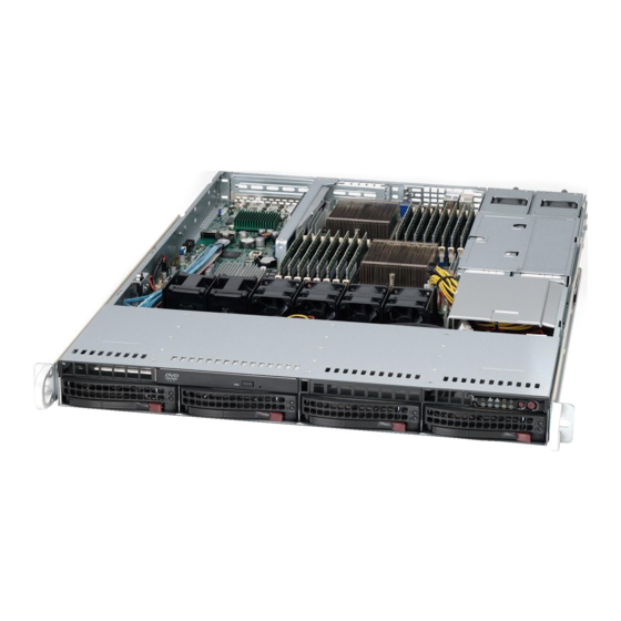
+ SE VER 1022G-URF User's Manual Figure 6-1. Chassis: Front and Rear Views Slim DVD-ROM Drive System LEDs Control Panel Hard Drive Bays System Reset Main Power Power Supply Modules USB Ports PCI Expansion Slots (w/ Riser Cards) Mouse/Keyboard Ports COM1 Port VGA Port Ethernet Ports Note: the SC815TQ-560UBP chassis (6016T-UF/6016T-NTF) has only a single... -
Page 81: System Fan Failure
3. Replace the failed fan with an identical 4-cm, 12 volt fan (available from Supermicro: p/n FAN-0086L4). 4. Push the new fan into the vacant space in the housing while making sure the arrows on the top of the fan (indicating air direction) point in the same... -
Page 82: Drive Bay Installation/Removal
+ SE VER 1022G-URF User's Manual 5. Reposition the fan housing back over the two mounting posts in the chassis, then reconnect the fan wires to the same chassis fan headers you removed them from. 6. Power up the system and check that the fan is working properly and that the LED on the control panel has turned off. -
Page 83: Hard Drive Installation
Chapter 6: Advanced Chassis Setup Hard Drive Installation The hard drives are mounted in drive carriers to simplify their installation and removal from the chassis. These carriers also help promote proper airflow for the drive bays. For this reason, even empty carriers without drives installed must remain in the chassis. -
Page 84: Dvd-Rom Drive Installation
+ SE VER 1022G-URF User's Manual Installing/Removing a Hard Drive 1. To remove a carrier, push the release button located beside the drive LEDs. 2. Swing the colored handle fully out and use it to pull the unit straight out (see Figure 6-5). -
Page 85: Power Supply
Power Supply The A+ SERVER 1022G-URF has a 700 watt redundant power supply configuration consisting of two hot-swap power modules. The power supply modules have an auto-switching capability, which enables them to automatically sense and operate with a 100V - 240V input voltage. - Page 86 Replace with the same model, which can be ordered directly from Supermicro (see Contact Information in the Preface). 1. First unplug the power cord from the failed power supply module.
-
Page 87: Chapter 7 Bios
BIOS Introduction This chapter describes the AMI BIOS Setup Utility for the A+ SERVER 1022G-URF. The AMI ROM BIOS is stored in a Flash EEPROM and can be easily updated. This chapter describes the basic navigation of the AMI BIOS Setup Utility setup screens. -
Page 88: System Time/System Date
A+ Server 1022G-URF User's Manual System Time/System Date You can edit this field to change the system time and date. Highlight System Time or System Date using the <Arrow> keys. Enter new values through the keyboard. Press the <Tab> key or the <Arrow> keys to move between fields. The date must be entered in DAY/MM/DD/YYYY format. - Page 89 Chapter 7: BIOS Watch Dog Function Allows system to restart when system is inactive more than 5-minutes. The options are Enabled and Disabled. Power Button Function This sets the function of the power button when you turn off the system. Options include 4-second Overide and Instant Off.
- Page 90 A+ Server 1022G-URF User's Manual Power Cap This option can decide the highest P-state in the OS. Options include P-state 0 through P-state 4. ACPI SRAT Table This option Enables or Disables the building of the ACPI SRAT Table. CPU Down Core This option sets down core support for the CPU.
- Page 91 Chapter 7: BIOS Bank Swizzle Mode This setting Enables or Disables the bank swizzle mode. ECC Configuration ECC Mode This submenu affects the DRAM scrub rate based on its setting. Options include Disabled, Basic, Good, Super, Max and User. Selecting User activates the other options for user setting.
- Page 92 A+ Server 1022G-URF User's Manual Legacy USB Support Select "Enabled" to enable the support for USB Legacy. Disable Legacy support if there are no USB devices installed in the system. "Auto" disabled Legacy support if no USB devices are connected. The options are Disabled, Enabled and Auto.
- Page 93 Chapter 7: BIOS Select "Disabled" to allow the data to be transferred from and to the device one sector at a time. Select "Auto" to allows the data transfer from and to the device occur multiple sectors at a time if the device supports it. The options are Auto and Disabled.
- Page 94 A+ Server 1022G-URF User's Manual PCI/PnP Configuration Clear NVRAM Select Yes to clear NVRAM during boot-up. The options are Yes and No. Plug & Play O/S Select Yes to allow the OS to configure Plug & Play devices. (This is not required for system boot if your system has an OS that supports Plug &...
- Page 95 Chapter 7: BIOS I/O port address and IRQ 4 for the interrupt address. Options include Disabled, 3F8/IRQ4, 3E8/IRQ4 and 2E8/IRQ3 Serial 2 Address This option specifies the base I/O port address and Interrupt Request address of serial port 2. Select "Disabled" to prevent the serial port from accessing any system resources.
- Page 96 A+ Server 1022G-URF User's Manual Terminal Type Selects the type of the target terminal. Options are ANSI, VT100 and VT-UTF8. VT-UTF8 Combo Key Support Allows you to Enable or Disable VT-UTF8 combination key support for ANSI/ VT100 terminals. Sredir Memory Display Delay Use this setting to set the delay in seconds to display memory information.
- Page 97 Chapter 7: BIOS ACPI APIC Support Determines whether to include the ACPI APIC table pointer in the RSDT pointer list. The available options are Enabled and Disabled. Headless Mode Use this setting to Enable or Disable headless operation mode through ACPI. ACPI Version Features Use this setting the determine which ACPI version to use.
- Page 98 A+ Server 1022G-URF User's Manual IP Address This submenu sets the IP address source as either Static or DHCP. Selecting Static allows you to manually set the IP Address, Subnet Mask and Gateway Address. In the field provided here enter the IP address in the decimal form of xxx.xxx.
-
Page 99: Security Menu
Chapter 7: BIOS SR56x0 (RD890S) PCIE Error Log This setting allows you set an error log ofr PCIE errors. Options include Yes or No. Security Menu AMI BIOS provides a Supervisor and a User password. If you use both passwords, the Supervisor password must be set first. -
Page 100: Exit Menu
A+ Server 1022G-URF User's Manual This feature allows you to specify the boot sequence from the list of available CD/ DVD drives. A device that is in parenthesis has been disabled in the corresponding type menu. Retry Boot Devices This option allows you to retry boot devices. Options include Enabled and Disabled. -
Page 101: Appendix A Bios Error Beep Codes
Appendix A: BIOS Error Beep Codes Appendix A BIOS Error Beep Codes During the POST (Power-On Self-Test) routines, which are performed each time the system is powered on, errors may occur. Non-fatal errors are those which, in most cases, allow the system to continue the boot-up process. - Page 102 + SE VER 1022G-URF User's Manual Notes...
-
Page 103: Appendix B Installing Windows
South Bridge RAID Settings before you install the Windows OS and other software drivers. To configure RAID settings, please refer to RAID Configuration User Guides posted on our web site at www.supermicro.com/support/manuals. Note: The following OS installation instructions are written for the Windows XP/2003 OS only. -
Page 104: B-2 Installing The Windows Os For A Non-Raid System
OS Setup will automatically load all device files and then continue with the OS installation. 14. After the Windows OS Installation is complete, the system will automatically reboot. 15. Insert the Supermicro Setup CD that came with your serverboard into the CD drive during system boot, and the main screen will display. -
Page 105: Appendix C System Specifications
Appendix C: System Specifications Appendix C System Specifications Processors Dual AMD Opteron 6000 series (AMD Socket G34 type) processors Note: You must install at least two processors for full functions to be supported. Note: Please refer to our web site for a complete listing of supported processors. Chipset One AMD SR5670 chipset and one SP5100 Southbridge chipset BIOS... - Page 106 + SE VER 1022G-URF User's Manual Expansion Slots One UIO card and one PCI Express x16 slot Serverboard H8DGU-F (Proprietary form factor) Dimensions: 12.28" x 13.05" (312 x 331 mm) Chassis SC815TQ-R700UBP Form Factor: 1U rackmount Dimensions: (WxHxD) 17 x 1.7 x 25.6 in. (432 x 43 x 650 mm) Weight Gross (Bare Bone): 43 lbs.
- Page 107 Appendix C: System Specifications Regulatory Compliance Electromagnetic Emissions: FCC Class A, EN 55022 Class A, EN 61000-3-2/- 3-3, CISPR 22 Class A Electromagnetic Immunity: EN 55024/CISPR 24, (EN 61000-4-2, EN 61000-4-3, EN 61000-4-4, EN 61000-4-5, EN 61000-4-6, EN 61000-4-8, EN 61000-4-11) Safety: CSA/EN/IEC/UL 60950-1 Compliant, UL or CSA Listed (USA and Canada), CE Marking (Europe) California Best Management Practices Regulations for Perchlorate Materials:...
- Page 108 VER 1022G-URF User's Manual (continued from front) The products sold by Supermicro are not intended for and will not be used in life support systems, medical equipment, nuclear facilities or systems, aircraft, aircraft devices, aircraft/emergency communication devices or other critical systems whose failure to perform be reasonably expected to result in significant injury or loss of life or catastrophic property damage.
Need help?
Do you have a question about the A+ SERVER 1022G-URF and is the answer not in the manual?
Questions and answers