
Related Manuals for Texas Instruments PGA308EVM


Summary of Contents for Texas Instruments PGA308EVM
- Page 1 PGA308EVM User's Guide Literature Number: SBOU060A July 2008 – Revised September 2016...
-
Page 2: Table Of Contents
Hardware Connections and Jumper Settings ................... Typical Hardware Connections ....................Connecting the Hardware ......................Connecting Power ............... Connecting the USB Cable to the PGA308EVM ......................Jumper Settings ....................PGA308 Software Overview ................Operating Systems for the PGA308 Software .................... PGA308EVM Software Install .................. - Page 3 Default Jumper Settings ................. 4-1. PGA308EVM Software—Functioning Properly ......... 4-2. PGA308EVM Software—No Communication with the USB DAQ Platform ......4-3. PGA308EVM Software—No Communication from USB DAQ Platform to PGA308 ......................4-4. PGA308 Controls ....................... 4-5. USB Controls ..................... 4-6. Current Revision of Software List of Tables .......................
-
Page 4: Preface
The following documents provide information regarding Texas Instruments integrated circuits used in the assembly of the PGA308EVM. These documents are available from the TI web site under the respective literature number (for example, SBxxnnn). Any letter appended to the literature number corresponds to the document revision that is current at the time of the writing of this User’s Guide. -
Page 5: Overview
Related Documentation from Texas Instruments. The PGA308EVM is an evaluation module that is used to fully evaluate the PGA308 device. The PGA308 is a mixed-signal programmable gain amplifier that has high resolution gain and offset adjustment capability. The PGA308EVM consists of two PCBs. One board generates the digital signals (USB DAQ Platform) required to communicate with the PGA308 (PGA308_Test_Board), and the second board contains the PGA308, as well as support and configuration circuitry. -
Page 6: Pga308Evm Hardware
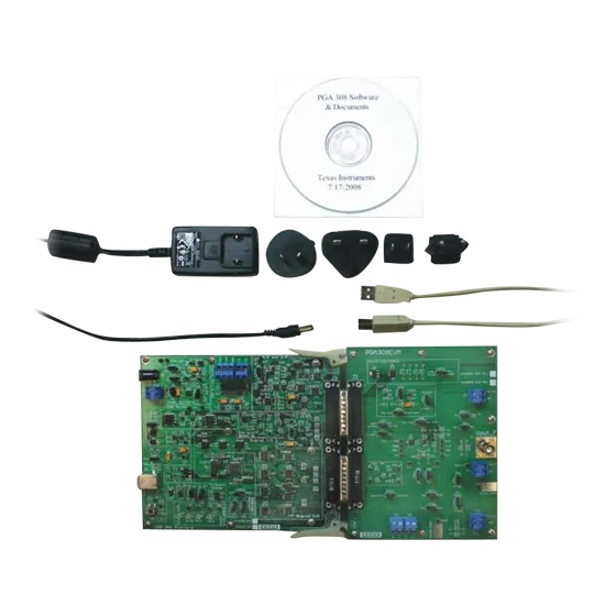
PGA308EVM Hardware Figure 1-1 shows the hardware included with the PGA308EVM kit. Contact the factory if any component is missing. TI highly recommendeds that you check the TI web site (at http://www.ti.com) to verify that you have the latest software. -
Page 7: System Setup
System Setup Figure 2-1 shows the system setup for the PGA308EVM. The PC runs software that communicates with the USB DAQ platform. The USB DAQ platform generates the digital signals used to communicate with the PGA308 test board. Connectors on the PGA308 test board allow for connection to the system that will be monitored by the user. -
Page 8: Theory Of Operation For The Pga308 Test Board Hardware
Figure 2-2. Block Diagram of the PGA308 Test Board SBOR004 for the PGA308 test board schematic, available for download at www.ti.com. System Setup SBOU060A – July 2008 – Revised September 2016 Submit Documentation Feedback Copyright © 2008–2016, Texas Instruments Incorporated... -
Page 9: Signal Definition Of J1 (25-Pin Male Dsub) On The Pga308 Test Board
Not used +15V Not used –15V Not used Ground SPI_SCK Not used SPI_CS1 Not used SPI_DOUT1 Not used SPI_DIN1 Not used SBOU060A – July 2008 – Revised September 2016 System Setup Submit Documentation Feedback Copyright © 2008–2016, Texas Instruments Incorporated... -
Page 10: Signal Definition Of J2 (25-Pin Female Dsub) On The Pga308 Test Board
Not used SPI_SCK Not used SPI_CS2 Not used SPI_DOUT2 Not used SPI_DIN2 Not used Not used Not used Not used Not used System Setup SBOU060A – July 2008 – Revised September 2016 Submit Documentation Feedback Copyright © 2008–2016, Texas Instruments Incorporated... -
Page 11: Theory Of Operation For The Usb Daq Platform
Theory of Operation For the USB DAQ Platform Figure 2-3 shows the block diagram for the USB DAQ platform. This platform is a general-purpose data acquisition system that is used on several different Texas Instruments evaluation modules. The block diagram shown in Figure 2-3 illustrates the general platform outline. -
Page 12: Hardware Connections And Jumper Settings
SBOU060A – July 2008 – Revised September 2016 Hardware Connections and Jumper Settings Many of the components on the PGA308EVM are susceptible to damage by electrostatic discharge (ESD). Customers are advised to observe proper ESD handling precautions when unpacking and handling the EVM, including the use of a grounded wrist strap at an approved ESD workstation. -
Page 13: Connecting The Hardware
Connecting the Hardware www.ti.com Connecting the Hardware The best way to connect the two PGA308EVM PCBs together is to gently push on both sides of the DSUB connectors, as shown in Figure 3-2. Make sure that the two connectors are completely socketed together;... -
Page 14: Connecting Power
Connecting Power www.ti.com Connecting Power Connect the two PGA308EVM PCBs before connecting a power source, as shown in Figure 3-3. Always connect power before connecting the USB cable. If the USB cable is connected before the power is supplied, the computer will attempt to communicate with an unpowered device, and the device will not be able to respond. -
Page 15: Connecting The Usb Cable To The Pga308Evm
Connecting the USB Cable to the PGA308EVM www.ti.com Connecting the USB Cable to the PGA308EVM Figure 3-4 shows the typical response to connecting the USB DAQ platform to a PC USB port for the first time. Note that the EVM must be powered up before connecting the USB cable. Typically, the computer will respond with a Found New Hardware, USB Device pop-up. -
Page 16: Jumper Settings
Jumper Settings Figure 3-5 shows the default jumper configuration for the PGA308EVM. In general, the jumper settings of the USB DAQ platform do not need to be changed. However, you may want to change some of the jumpers on the PGA308 test board to match your specific device configuration (for example, to change the reference configuration). -
Page 17: Pga308 Test Board Jumper Function
CLAMP JMP11 Dout input. JMP16 Divider divider or Ext V CLAMP CLAMP CLAMP SBOU060A – July 2008 – Revised September 2016 Hardware Connections and Jumper Settings Submit Documentation Feedback Copyright © 2008–2016, Texas Instruments Incorporated... -
Page 18: Usb Daq Platform Jumper Settings (5-V Power Supply)
L or H. This jumper sets the USB DAQ platform USB address. JUMP5 L or H. This jumper sets the USB DAQ platform USB address. Hardware Connections and Jumper Settings SBOU060A – July 2008 – Revised September 2016 Submit Documentation Feedback Copyright © 2008–2016, Texas Instruments Incorporated... -
Page 19: Pga308 Software Overview
PGA308EVM Software Install Install the PGA308EVM software by following these steps: 1. Software can be downloaded from the PGA308EVM web page, or from the disk included with the PGA308EVM, which contains a folder called Install_software/. 2. Find the file called setup.exe. Double-click the file to start the installation process. -
Page 20: Starting The Pga308Evm Software
Use the Windows Start menu to start the PGA308 software. From Start, select All Programs, then select the PGA308EVM program. Figure 4-1 shows the software display if the EVM is functioning properly. Figure 4-1. PGA308EVM Software—Functioning Properly PGA308 Software Overview SBOU060A – July 2008 – Revised September 2016 Submit Documentation Feedback... -
Page 21: Pga308Evm Software-No Communication With The Usb Daq Platform
USB device is properly connected to a PC with the Windows operating system. Figure 4-2. PGA308EVM Software—No Communication with the USB DAQ Platform SBOU060A – July 2008 – Revised September 2016 PGA308 Software Overview Submit Documentation Feedback Copyright ©... -
Page 22: Pga308Evm Software-No Communication From Usb Daq Platform To Pga308
DSUB connectors are completely pushed together. Another possible cause for this error is it that the PGA308 test board jumpers are set in the wrong positions. Figure 4-3. PGA308EVM Software—No Communication from USB DAQ Platform to PGA308 PGA308 Software Overview SBOU060A –... -
Page 23: Using The Pga308 Software
Using the PGA308 Software The PGA308EVM software has six different tabs that allow you to access different features of the PGA308. Each of these tabs are intended to have an intuitive graphical interface that allows users to develop a better understanding of the PGA308. -
Page 24: Evm Pull-Down Menus
One-Wire, DAC, and ADC control are possible through this feature. Figure 4-5 illustrates the USB controls. Figure 4-5. USB Controls PGA308 Software Overview SBOU060A – July 2008 – Revised September 2016 Submit Documentation Feedback Copyright © 2008–2016, Texas Instruments Incorporated... -
Page 25: Help
The About feature can be used to check the current revision. This document is based on revision 1.2.17, as shown in Figure 4-6. Figure 4-6. Current Revision of Software SBOU060A – July 2008 – Revised September 2016 PGA308 Software Overview Submit Documentation Feedback Copyright © 2008–2016, Texas Instruments Incorporated... -
Page 26: A Bill Of Materials
1% 0603 SMD Resistor 6.04kΩ 1/10W µF Panasonic - ECG ERJ-3EKF6041V 1% 0603 SMD Omit µF R17, R18 Omit — — Bill of Materials SBOU060A – July 2008 – Revised September 2016 Submit Documentation Feedback Copyright © 2008–2016, Texas Instruments Incorporated... -
Page 27: Active Devices And Miscellaneous
0.250" OD, aluminum iridite finish Machine screw, 4–40´3/8" Screws Phillips PanHead, steel, zinc Building Fasteners PMS 440 0038 PH plated SBOU060A – July 2008 – Revised September 2016 Bill of Materials Submit Documentation Feedback Copyright © 2008–2016, Texas Instruments Incorporated... -
Page 28: Revision History
Changes from Original (July, 2008) to A Revision ......................Page ........................• Changed Figure 1-1 ..............• Deleted Quick Start Video from list of PGA308EVM Hardware Revision History SBOU060A – July 2008 – Revised September 2016 Submit Documentation Feedback Copyright © 2008–2016, Texas Instruments Incorporated... - Page 29 STANDARD TERMS AND CONDITIONS FOR EVALUATION MODULES Delivery: TI delivers TI evaluation boards, kits, or modules, including demonstration software, components, and/or documentation which may be provided together or separately (collectively, an “EVM” or “EVMs”) to the User (“User”) in accordance with the terms and conditions set forth herein.
- Page 30 FCC Interference Statement for Class B EVM devices NOTE: This equipment has been tested and found to comply with the limits for a Class B digital device, pursuant to part 15 of the FCC Rules. These limits are designed to provide reasonable protection against harmful interference in a residential installation.
- Page 31 【無線電波を送信する製品の開発キットをお使いになる際の注意事項】 開発キットの中には技術基準適合証明を受けて いないものがあります。 技術適合証明を受けていないもののご使用に際しては、電波法遵守のため、以下のいずれかの 措置を取っていただく必要がありますのでご注意ください。 1. 電波法施行規則第6条第1項第1号に基づく平成18年3月28日総務省告示第173号で定められた電波暗室等の試験設備でご使用 いただく。 2. 実験局の免許を取得後ご使用いただく。 3. 技術基準適合証明を取得後ご使用いただく。 なお、本製品は、上記の「ご使用にあたっての注意」を譲渡先、移転先に通知しない限り、譲渡、移転できないものとします。 上記を遵守頂けない場合は、電波法の罰則が適用される可能性があることをご留意ください。 日本テキサス・イ ンスツルメンツ株式会社 東京都新宿区西新宿6丁目24番1号 西新宿三井ビル 3.3.3 Notice for EVMs for Power Line Communication: Please see http://www.tij.co.jp/lsds/ti_ja/general/eStore/notice_02.page 電力線搬送波通信についての開発キットをお使いになる際の注意事項については、次のところをご覧ください。http:/ /www.tij.co.jp/lsds/ti_ja/general/eStore/notice_02.page SPACER EVM Use Restrictions and Warnings: 4.1 EVMS ARE NOT FOR USE IN FUNCTIONAL SAFETY AND/OR SAFETY CRITICAL EVALUATIONS, INCLUDING BUT NOT LIMITED TO EVALUATIONS OF LIFE SUPPORT APPLICATIONS.
- Page 32 Notwithstanding the foregoing, any judgment may be enforced in any United States or foreign court, and TI may seek injunctive relief in any United States or foreign court. Mailing Address: Texas Instruments, Post Office Box 655303, Dallas, Texas 75265 Copyright © 2016, Texas Instruments Incorporated...
- Page 33 IMPORTANT NOTICE Texas Instruments Incorporated and its subsidiaries (TI) reserve the right to make corrections, enhancements, improvements and other changes to its semiconductor products and services per JESD46, latest issue, and to discontinue any product or service per JESD48, latest issue.
Need help?
Do you have a question about the PGA308EVM and is the answer not in the manual?
Questions and answers