Table of Contents
Advertisement
Quick Links
Advertisement
Table of Contents

Related Manuals for Texas Instruments PGA308


Summary of Contents for Texas Instruments PGA308
- Page 1 PGA308EVM User's Guide Literature Number: SBOU060 July 2008...
- Page 2 SBOU060 – July 2008 Submit Documentation Feedback...
-
Page 3: Table Of Contents
System Setup ............Theory of Operation for the PGA308 Test Board Hardware ........... Signal Definition of J1 (25-Pin Male DSUB) on the PGA308 Test Board ........Signal Definition of J2 (25-Pin Female DSUB) on the PGA308 Test Board ..............Theory of Operation For the USB DAQ Platform ............... - Page 4 ....................Default Jumper Settings ................. PGA308EVM Software—Functioning Properly ......... PGA308EVM Software—No Communication with the USB DAQ Platform ......PGA308EVM Software—No Communication from USB DAQ Platform to PGA308 ......................PGA309 Controls ....................... USB Controls ..................... Current Revision of Software List of Tables .....................
-
Page 5: Preface
User’s Guide. Newer revisions may be available from the TI web site at www.ti.com, or call the Texas Instruments Literature Response Center at (800) 477-8924 or the Product Information Center at (972) 644-5580. When ordering, identify the document by both title and literature number. - Page 6 SBOU060 – July 2008 Submit Documentation Feedback...
-
Page 7: Overview
Instruments web site at www.ti.com. Support documents are listed in the section of this guide entitled Related Documentation from Texas Instruments. The PGA308EVM is an evaluation module that is used to fully evaluate the PGA308 device. The PGA308 is a mixed-signal programmable gain amplifier that has high resolution gain and offset adjustment capability. -
Page 8: Pga308Evm Hardware
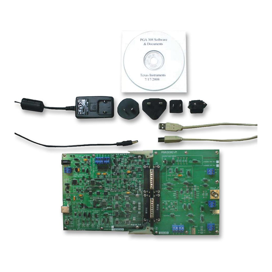
It is also recommended that you watch the QuickStart Video (included on the compact disk) before using the PGA308EVM. The complete kit includes the following items: • PGA308 test PCB • USB DAQ platform PCB • USB cable •... -
Page 9: System Setup
PGA308EVM. The PC runs software that communicates with the USB DAQ platform. The USB DAQ platform generates the digital signals used to communicate with the PGA308 test board. Connectors on the PGA308 test board allow for connection to the system that will be monitored by the user. -
Page 10: Theory Of Operation For The Pga308 Test Board Hardware
Theory of Operation for the PGA308 Test Board Hardware Figure 2-2 shows the block diagram of the PGA308 test board. The PGA308 test board functionality is relatively simple. It provides connections to the one-wire interface, digital-to-analog converter (DAC), analog-to-digital converter (ADC), and general-purpose inputs/outputs (GPIOs) on the USB DAQ platform. -
Page 11: Signal Definition Of J1 (25-Pin Male Dsub) On The Pga308 Test Board
J1 on the PGA308 test board. Table 2-1 also identifies signals connected to pins on J1 that are not used on the PGA308 test board. Table 2-1. Signal Definition of J1 Signal Name from USB... -
Page 12: Signal Definition Of J2 (25-Pin Female Dsub) On The Pga308 Test Board
J2 on the PGA308 test board. Table 2-2 also identifies signals connected to pins on J2 that are not used on the PGA308 test board. Table 2-2. Signal Definition of J2 Signal Name from USB... -
Page 13: Theory Of Operation For The Usb Daq Platform
Theory of Operation For the USB DAQ Platform Figure 2-3 shows the block diagram for the USB DAQ platform. This platform is a general-purpose data acquisition system that is used on several different Texas Instruments evaluation modules. The block diagram shown in Figure 2-3 illustrates the general platform outline. - Page 14 System Setup SBOU060 – July 2008 Submit Documentation Feedback...
-
Page 15: Hardware Connections And Jumper Settings
Typical Hardware Connections A typical PGA308EVM hardware setup connects the two EVM PCBs, then supplies power and connects an external shunt and load. The external connections may be the real-world system to which the PGA308 will be connected. Figure 3-1 shows the typical hardware connections. -
Page 16: Connecting The Hardware
Connecting the Hardware www.ti.com Connecting the Hardware The best way to connect the two PGA308EVM PCBs together is to gently push on both sides of the DSUB connectors, as shown in Figure 3-2. Make sure that the two connectors are completely socketed together; loose connections may cause intermittent EVM operation. -
Page 17: Connecting Power
Connecting Power www.ti.com Connecting Power Connect the two PGA308EVM PCBs before connecting a power source, as shown in Figure 3-3. Always connect power before connecting the USB cable. If the USB cable is connected before the power is supplied, the computer will attempt to communicate with an unpowered device, and the device will not be able to respond. -
Page 18: Connecting The Usb Cable To The Pga308Evm
Connecting the USB Cable to the PGA308EVM www.ti.com Connecting the USB Cable to the PGA308EVM Figure 3-4 shows the typical response to connecting the USB DAQ platform to a PC USB port for the first time. Note that the EVM must be powered up before connecting the USB cable. Typically, the computer will respond with a Found New Hardware, USB Device pop-up. -
Page 19: Jumper Settings
PGA308EVM. In general, the jumper settings of the USB DAQ platform do not need to be changed. However, you may want to change some of the jumpers on the PGA308 test board to match your specific device configuration (for example, to change the reference configuration). -
Page 20: Pga308 Test Board Jumper Function
JMP9 ADS– PGA308 input. Note that the ADC has a switched capacitor input, so it can affect the input signal. It is recommended that ADCs be disconnected when using a real-world sensor. ADS+ or NC allows you to connect or disconnect the ADC on the USB DAQ platform to the... -
Page 21: Usb Daq Platform Jumper Settings (5V Power Supply)
Jumper Settings www.ti.com Table 3-2 summarizes the function of the USB DAQ platform jumpers. For most applications, the default jumper position should be used. A separate document (SBOU056) gives details regarding the operation and design of the USB DAQ platform. Table 3-2. - Page 22 Hardware Connections and Jumper Settings SBOU060 – July 2008 Submit Documentation Feedback...
-
Page 23: Pga308 Software Overview
3. Follow the on-screen prompts to install the software. 4. To remove the application, use the Windows Control Panel utility, Add/Remove Software. 5. The PGA308 Quickstart Video (included on the CD), or available at www.ti.com, gives more details regarding the initialization of the software. -
Page 24: Starting The Pga308Evm Software
Starting the PGA308EVM Software www.ti.com Starting the PGA308EVM Software Use the Windows Start menu to start the PGA308 software. From Start, select All Programs, then select the PGA308EVM program. Figure 4-1 shows the software display if the EVM is functioning properly. -
Page 25: Pga308Evm Software-No Communication With The Usb Daq Platform
USB device is properly connected to a PC with the Windows operating system. Figure 4-2. PGA308EVM Software—No Communication with the USB DAQ Platform SBOU060 – July 2008 PGA308 Software Overview Submit Documentation Feedback... -
Page 26: Pga308Evm Software-No Communication From Usb Daq Platform To Pga308
Figure 4-3 shows an error that will occur if the PGA308 test board is not communicating with the USB DAQ platform. If you get this error, check the connectors between the two boards; make sure the two 25-pin DSUB connectors are completely pushed together. Another possible cause for this error is it that the PGA308 test board jumpers are set in the wrong positions. -
Page 27: Using The Pga308 Software
The PGA308EVM software has six different tabs that allow you to access different features of the PGA308. Each of these tabs are intended to have an intuitive graphical interface that allows users to develop a better understanding of the PGA308. -
Page 28: Evm Pull-Down Menus
EVM Pull-Down Menus 4.5.1 PGA308 Controls The PGA308 configuration (such as register settings) can be saved or loaded using the EVM Controls pull-down menu, as shown in Figure 4-4. The file that the configuration is saved into is a simple text file and can be viewed with any text editor. -
Page 29: Help
4.5.3 Help The About feature can be used to check the current revision. This document is based on revision 1.2.17, as shown in Figure 4-6. Figure 4-6. Current Revision of Software SBOU060 – July 2008 PGA308 Software Overview Submit Documentation Feedback... - Page 30 PGA308 Software Overview SBOU060 – July 2008 Submit Documentation Feedback...
-
Page 31: A Bill Of Materials
Appendix A SBOU060 – July 2008 Bill of Materials Resistors and Capacitors Value Ref Des Description Vendor Part Number Capacitor Tantalum 4.7µF 25V 4.7µF Kemet T491C475K025AT 10% SMD 6032-28 (EIA) Capacitor 0.10µF 25V 0.1µF C6–C15 Kemet CC0603ZRY5V8BB104 CERAMIC Y5V 0603 Capacitor 10000pF 50V 10nF C3, C5... -
Page 32: Active Devices And Miscellaneous
Ref Des Description Vendor Part Number CONN JACK BNC VERT 50Ω Tyco 5227699-1 Electronics/Amp IC OP AMP 1.8V 0-DRIFT OPA333AIDBVT Texas Instruments OPA333AIDBVT SOT23-5 IC LDO VOLT REF 4.096V REF3240 Texas Instruments REF3240AIDBVT SOT23-6 IC LDO VOLT REF 2.5V REF3225... - Page 33 EVALUATION BOARD/KIT IMPORTANT NOTICE Texas Instruments (TI) provides the enclosed product(s) under the following conditions: This evaluation board/kit is intended for use for ENGINEERING DEVELOPMENT, DEMONSTRATION, OR EVALUATION PURPOSES ONLY and is not considered by TI to be a finished end-product fit for general consumer use. Persons handling the product(s) must have electronics training and observe good engineering practice standards.
-
Page 34: Important Notices
IMPORTANT NOTICE Texas Instruments Incorporated and its subsidiaries (TI) reserve the right to make corrections, modifications, enhancements, improvements, and other changes to its products and services at any time and to discontinue any product or service without notice. Customers should obtain the latest relevant information before placing orders and should verify that such information is current and complete. - Page 35 Mouser Electronics Authorized Distributor Click to View Pricing, Inventory, Delivery & Lifecycle Information: Texas Instruments PGA308EVM...
Need help?
Do you have a question about the PGA308 and is the answer not in the manual?
Questions and answers