Table of Contents
Advertisement
Quick Links
PGA460 Frequently Asked Questions (FAQ) and EVM
Akeem Whitehead
This document is intended to answer the most common and frequently asked questions (FAQs) that users
have when evaluating the PGA460 or PGA460-Q1 EVM and GUI. Step-by-step procedures to hardware
troubleshooting and software debugging areprovided. Recommendations to improve performance and
best practices to prevent device failure, GUI errors, or improper measurement techniques are also
discussed.
......................................................................................................................
1
2
2.1
2.2
2.3
2.4
3
3.1
3.2
3.3
3.4
3.5
3.6
4
4.1
(CSS) drivers mentioned in the Quick Start video. Are these driver files important?
4.2
4.3
I cannot open the GUI. A Windows dialog box immediately opens stating, PGA460Q1EVM GUI
has stopped working
4.4
5
5.1
5.2
5.3
5.4
5.5
5.6
5.7
5.8
5.9
5.10
5.11
SLAA733 - May 2017
Submit Documentation Feedback
ABSTRACT
Contents
......................................................................................
..................................................................................................
....................................................................................................
...........................................................................................
.........................................................................
............................................................................................
...............................................................................................
...........................................................................................
......................................................................................................
.....................................................................................................
PGA460 Frequently Asked Questions (FAQ) and EVM Troubleshooting
Copyright © 2017, Texas Instruments Incorporated
Troubleshooting Guide
......................................
.....................................................
...................................................................
.....................................................
.........................................................
...................................................................
................................................................
....................................................
..............................................
................................................
Application Report
SLAA733 - May 2017
......................
...........................
.................
.................................
......................
10
14
14
.....................
14
15
16
......
16
17
20
20
20
...................
21
Guide
3
3
3
3
3
4
5
5
5
5
6
7
7
7
7
9
9
1
Advertisement
Table of Contents

Related Manuals for Texas Instruments PGA460


Summary of Contents for Texas Instruments PGA460
-
Page 1: Table Of Contents
..............Can I automatically set the time varying gain? ..Can I evaluate multiple PGA460 devices using the same UART bus of the PGA460-Q1 EVM? The ultrasonic measurement result data is random, very short, always the maximum value, or ..................... - Page 2 A false echo positive is always present at 7.7 m, even when the transducer is disconnected. Why ........does the PGA460 detect this unreal artifact on the echo data dump? 6.3. Motor switching noise appears to be coupling onto the ultrasonic return path, which ....
-
Page 3: Overview
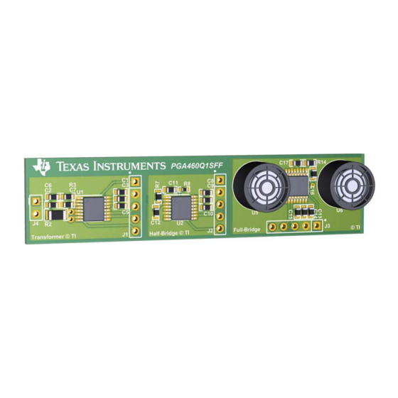
PGA460Q1SFF reference design (to be released) is available as an example for the small form factor (SFF) size for a PGA460 solution, and offers three variants. The variants include a transformer-driven twisted-pair closed-top transducer, a half- bridge-driven surface-mount open-top transducer, and a full-bridge-driven radial lead bi-static pair on this three-in-one reference design. -
Page 4: How Can I Prepare For Mass Production Programming And System Integration
The GUI primarily uses UART to evaluate the PGA460. However, TCI and One-Wire UART can also be used to fully program and evaluate the PGA460. The GUI uses TI’s USB2 ANY proprietary code to communicate from a PC to the PGA460 device. The GUI source code is not available to the public. Instead, the... -
Page 5: Hardware Installation And Setup
The shunt is not required to operate the EVM. The shunt is recommended for quick out-of-box evaluation of the PGA460-Q1 EVM when installed in theLP-USB mode, and using only a computer or laptop to power and communicate with the EVM. However, the boost-circuit to power the PGA460 will limit the long range performance of the transformer driven mode. -
Page 6: The Closed-Top Twisted Pair Transducer Hangs From The Daughtercard, And Tends To Points Down
How do you recommend I mount the transducer with a support or stand? Initially, use the packaging sponge from the box the BOOSTXL-PGA460 was shipped in as mounting material for the twisted pair transducer. Cut out a 5 cm × 5 cm square of sponge, and puncture the center with a pen sized hole. -
Page 7: Is A Transducer's Pin Polarity Important
During installation, I was not prompted to install the MSP430 and Code Composer Studio™ (CSS) drivers mentioned in the Quick Start video. Are these driver files SLAA733 – May 2017 PGA460 Frequently Asked Questions (FAQ) and EVM Troubleshooting Guide Submit Documentation Feedback... -
Page 8: Uniflash Session Details
USB_eZ-RF, and will only install on a 64-bit version of Windows 7 or newer. Before reading the remainder of this answer, try loading the batch file using the PGA460-Q1 EVM GUI. If you are able to successfully load the batch file, then the drivers were installed without prompts, or the PC had previously installed the same driver files. -
Page 9: The Boostxlpga460-Firmware.bat Batch File Fails To Install
PGA460Q1EVM-x.x.x.x.exe must be run from the same folder containing the USB2 ANY.dll and Microsoft.VisualBasic.PowerPacks.Vs.dll. These DLL files are installed in the same path as the executable when using the PGA460-Q1 EVM GUI install wizard. The GUI depends on these two DLL files to initialize and function properly. -
Page 10: Hardware Modifications
Tuning capacitors are not required for direct-driven transducers. Transducer Substitution Alternative Transducer Sockets Figure 11. Direct Driven Transducer Substitution PGA460 Frequently Asked Questions (FAQ) and EVM Troubleshooting SLAA733 – May 2017 Guide Submit Documentation Feedback Copyright © 2017, Texas Instruments Incorporated... -
Page 11: Enabling Bi-Static Mode On Daughtercard
The direct driven circuit is limited to 60 V in full-bridge mode because the OUTA and OUTB pins of the PGA460 are rated for an absolute maximum of 30 V. The overall loss in driver strengths yields a shorter detectable range. -
Page 12: Full-Bridge Bi-Static Mode Modifications
Yes, the PGA460 can be supplied with a smaller or larger voltage versus the voltage sinking through the OUTA and OUTB pins. For example, the VPWR pin of the PGA460 can be supplied with the minimum of 6 V, while the transformer’s center-tap or direct driver’s high-side reference is at 30 V. Conversely, the VPWR pin of the PGA460 can be supplied with the maximum of 28 V, while the transformer center-tap or direct driver high-side reference is at 6 V (or even lower). -
Page 13: Horn To Focus Field-Of-View
Figure 14. Horn to Focus Field-of-View 4.4.10 Can I use the IOREG or AVDD rails of the internal PGA460 regulators to power other components or microcontrollers? The AVDD and IOREG regulators are not intended to support any external load. AVDD is very sensitive to load changes because it is used as a precision voltage reference, current bias, and internal clocking. -
Page 14: Running The Software
For this reason, the PGA460 was set with the typical maximum limit of 11.2m for a BAL or LO single command. How can I detect more than eight objects? Can I set the threshold to ignore ringing... -
Page 15: Can I Automatically Set The Threshold Map
Figure 17. Maximizing the Threshold Level to Ignore Ultrasonic Activity Can I automatically set the threshold map? The PGA460 does not implement automatic threshold mapping, but the master controller can implement a function to set the threshold based on the average echo data dump of a no-object burst-and-listen (NOBAL) profile. -
Page 16: Can I Automatically Set The Time Varying Gain
Can I evaluate multiple PGA460 devices using the same UART bus of the PGA460-Q1 EVM? Yes, the GUI can be set to communicate with any PGA460 UART address, with a default UART address of 0 out of 7. To communicate to a non-0 UART address, navigate to the Interface Mode page, and select the UART Interface Address from the dropdown menu of the Command Selection box. -
Page 17: The Ultrasonic Measurement Result Data Is Random, Very Short, Always The Maximum Value, Or Never Updates
If an external PGA460 is connected to the BOOSTXL-PGA460 BoosterPack UART terminal, communication to the PGA460 installed on the BOOSTXL-PGA460 can be disabled by navigating to the Edit tab of the window menu, and clicking the Disable BOOSTXL-PGA460 Communication option. This allows communication commands to still transmit from the MSP-EXP430F5529LP, but prevents the master issued commands from reaching the on-board PGA460. -
Page 18: Mid-Code Threshold Times And Levels
Alternatively, set the initial gain to a larger value such that the ramping is saturated, and does not trigger the threshold. PGA460 Frequently Asked Questions (FAQ) and EVM Troubleshooting SLAA733 – May 2017 Guide Submit Documentation Feedback Copyright ©... -
Page 19: Dsp Output Ramp Triggering A False Positive
Radically dropped TVG level after forced saturation of burst Figure 24. TVG Max-to-Min Trough to Saturate Initial Burst of Echo Data Dump SLAA733 – May 2017 PGA460 Frequently Asked Questions (FAQ) and EVM Troubleshooting Guide Submit Documentation Feedback Copyright © 2017, Texas Instruments Incorporated... -
Page 20: The Noise Floor Increases Significantly At Long Distances
Memory Map page of the GUI, and click the Save Grid icon. This will save the latest values of the PGA460 memory to a text (.txt) file, which can be loaded onto other PGA460 devices when using the GUI. To ensure the latest device settings are pulled from the device, click the Read All icon before saving the grid. -
Page 21: 5.10 How Do I Successfully Use A High-Frequency Transducer (180-480Khz) With The Gui
Figure 26. UtilitiesTime-of-Flight Converter • Is the PGA460 drive and receive frequency set to the same resonant frequency of the transducer? If the transducer is driven at a frequency outside of its resonant or center-frequency, then the transducer will not be generate any sound pressure level. Most transducers typically allow for ±5 kHz drive and receive drift before no measurable returns are detected and filtered out by the band-pass filter of the DSP. -
Page 22: How Do I Calculate The Distance Using The Return Data From The Ultrasonic Measurement Results
= distance / time. Because the speed of sound (velocity) is typically at a value of 343 m/s at room temperature, and the PGA460 outputs the round-trip time at which the threshold is intersected in 1us resolution after bursting, the distance to the object is computed as the product of velocity and one-way time. -
Page 23: 5.12 Is There Any Limitation In Using One-Wire Uart (Owu) Mode On The Gui
The GUI currently does not support evaluation of the One-Wire UART interface, though the hardware is in place to do so for future GUI updates. The GUI is able to set the PGA460 device into the One-Wire UART mode, but the GUI will only be able to transmit data. GUI is not able to process the return data once the OWU mode is set. -
Page 24: Motor Switching Noise Appears To Be Coupling Onto The Ultrasonic Return Path, Which Increases The Noise Floor. How Do I Mitigate This Noisy Loading Effect Of The Motors
100Ω to 3kΩ. The addition of a series resistance improves noise rejection and filtering at the input of the return path to the PGA460 AFE without impeding peak return performance. This additional resistance will also improve bulk current-injection (BCI) robustness. -
Page 25: In Transformer Driven Mode, The Secondary Voltage Appears As A Distorted Sinusoidal Waveform
8 kHz beyond the nominal center frequency of the transducer will prevent the PGA460 noise floor from saturating. If the switching frequency is greater than the resonant frequency, there is no likelihood that harmonics will interfere with the transducer performance. -
Page 26: Does The Usb-Boost Circuit Limit My Sensor's Overall Driver Strength
The frequency diagnostic feature of the transducer enables the PGA460 to measure the resonant frequency of the transducer during post-burst decay. This can be used to find or optimize the PGA460 driving frequency to match the resonant frequency of the transducer to produce the maximum amount of sound pressure level for long range applications. -
Page 27: When Should I Use The Disable Current Limit Feature
When using the USB boost circuit to power the PGA460-Q1 EVM, the AC power adapter of the laptop may raise the noise floor of the PGA460. This ultimately depends on how stable the AC power adapter is. To prevent the AC power adapter from possibly influencing the noise floor, isolate and power the laptop from battery only. - Page 28 IMPORTANT NOTICE FOR TI DESIGN INFORMATION AND RESOURCES Texas Instruments Incorporated (‘TI”) technical, application or other design advice, services or information, including, but not limited to, reference designs and materials relating to evaluation modules, (collectively, “TI Resources”) are intended to assist designers who are developing applications that incorporate TI products;...
Need help?
Do you have a question about the PGA460 and is the answer not in the manual?
Questions and answers