Table of Contents
Advertisement
Quick Links
PGA5807A, 8-Channel, High-Bandwidth, Analog Front-End
This user's guide gives a general overview of the PGA5807A evaluation module (EVM) and provides a
general description of the features and functions to be considered while using this module. This manual is
applicable to the PGA5807A analog front-end. The PGA5807A EVM provides a platform for evaluating the
ADC under various signal, clock, reference, and ADC output formats.
1
2
2.1
2.2
3
3.1
3.2
3.3
4
4.1
4.2
4.3
4.4
5
5.1
5.2
5.3
6
7
8
1
Evaluation Setup
2
HSDCpro Install (a)
3
HSDCpro Install (b)
4
HSDCpro Install (c)
5
HSDCpro Install (d)
6
HSDCpro Install (e)
7
HSDCpro Install (f)
8
HSDCpro Install (g)
9
HSDCpro Install (h)
10
HSDCpro Install (i)
11
PGA5807 GUI Install (a)
12
PGA5807 GUI Install (b)
13
PGA5807 GUI Install (c)
14
PGA5807 GUI Install (d)
15
PGA5807 GUI Install (e)
SLAU538 - October 2013
Submit Documentation Feedback
...........................................................................................
..................................................................................................
..............................................................................
............................................................................................
.............................................................................................
...........................................................................
................................................................................
...................................................................................................
................................................................................................
......................................................................................................
.....................................................................................................
............................................................................................
........................................................................................
..................................................................................................
List of Figures
............................................................................................................
.........................................................................................................
.........................................................................................................
.........................................................................................................
.........................................................................................................
.........................................................................................................
..........................................................................................................
.........................................................................................................
.........................................................................................................
..........................................................................................................
..................................................................................................
..................................................................................................
..................................................................................................
..................................................................................................
..................................................................................................
PGA5807A, 8-Channel, High-Bandwidth, Analog Front-End Evaluation
Copyright © 2013, Texas Instruments Incorporated
Evaluation Module
Contents
....................................................................
.......................................................................
..................................................................
..............................................................
....................................................
User's Guide
SLAU538 - October 2013
4
5
..........................
5
10
14
15
16
18
19
19
24
28
32
37
38
39
43
44
60
63
4
5
6
6
7
7
8
8
9
9
10
10
11
11
12
1
Module
Advertisement
Table of Contents

Subscribe to Our Youtube Channel
Related Manuals for Texas Instruments PGA5807A


Summary of Contents for Texas Instruments PGA5807A
-
Page 1: Table Of Contents
PGA5807A, 8-Channel, High-Bandwidth, Analog Front-End Evaluation Module This user’s guide gives a general overview of the PGA5807A evaluation module (EVM) and provides a general description of the features and functions to be considered while using this module. This manual is applicable to the PGA5807A analog front-end. - Page 2 PGA5807 GUI Setup for PGA5807A + ADS5296A 1 ............PGA5807A + ADS5296A SNR, THD, Gain Test Capture 1 ........PGA5807 GUI Setup for PGA5807A + ADS5296A SNR, THD, Gain Test 2 ................ PGA5807A + ADS5296A Gain Test Capture 2 ............
- Page 3 ..........PGA5807A Schematic, (Sh. 3 of 16), ADS5296A Sampling Clock ........... PGA5807A Schematic, (Sh. 4 of 16), PGA5807A Analog Inputs Ch1-4 ........... PGA5807A Schematic, (Sh. 5 of 16), PGA5807A Analog Inputs Ch5-8 ............PGA5807A Schematic, (Sh. 6 of 16), PGA_CH1, ADC_CH5 ............
-
Page 4: Quick View Of Evaluation Setup
PGA5807A EVM: The PGA5807A EVM contains both the PGA5807A device and the ADS5296A ADC from Texas Instruments. With this, a complete signal chain can be evaluated with the output of the ADS5296A ADC being captured by the TSW1400 EVM. The EVM is configured to allow for the following without any hardware changes required: testing stand-alone PGA5807A, testing stand-alone ADS5296A, or testing cascaded PGA5807A plus ADS5296A. -
Page 5: Gui Software Installation
Power Supply: A +5-V supply powers the PGA5807A EVM through connectors J21(+5V) and J25(GND) providing power to both the PGA5807A and ADS296 devices. The positive power supply must be able to source up to 1.5 A. A –5-V (negative) supply is required to provide power to amplifiers on the EVM when testing the PGA5807A in stand-alone mode only. - Page 6 Next button as shown in Figure Figure 3. HSDCpro Install (b) • Read the License Agreement from Texas Instruments and select I accept the License Agreement and press the Next button as shown in Figure Figure 4. HSDCpro Install (c) PGA5807A, 8-Channel, High-Bandwidth, Analog Front-End Evaluation SLAU538 –...
- Page 7 Figure Figure 5. HSDCpro Install (d) • Press the Next button as shown in Figure Figure 6. HSDCpro Install (e) SLAU538 – October 2013 PGA5807A, 8-Channel, High-Bandwidth, Analog Front-End Evaluation Module Submit Documentation Feedback Copyright © 2013, Texas Instruments Incorporated...
- Page 8 • The window shown in Figure 8 appears indicating Installation Complete. Press the Next button. Figure 8. HSDCpro Install (g) PGA5807A, 8-Channel, High-Bandwidth, Analog Front-End Evaluation SLAU538 – October 2013 Module Submit Documentation Feedback Copyright © 2013, Texas Instruments Incorporated...
- Page 9 National Instruments’ MCR installer. If requested, hit the Restart button to complete the installation. Figure 10. HSDCpro Install (i) SLAU538 – October 2013 PGA5807A, 8-Channel, High-Bandwidth, Analog Front-End Evaluation Module Submit Documentation Feedback Copyright © 2013, Texas Instruments Incorporated...
-
Page 10: Pga5807A Evm Gui Installation
PGA5807A EVM GUI Installation From the Texas Instruments website, www.ti.com, search for PGA5807AEVM. Clicking on the hyperlink in the table will lead to another link titled PGA5807 GUI Installer, v1.0. Click on this link to download and save the zipped file (slac571.zip). - Page 11 GUI Software Installation www.ti.com • Read the License Agreement from Texas Instruments and select the I accept the License Agreement button and then press the Next button as shown in Figure Figure 13. PGA5807 GUI Install (c) • Read the License Agreement from National Instruments and select the I accept the License Agreement...
- Page 12 The window shown in Figure 16 should appear showing that installation is in progress. Figure 16. PGA5807 GUI Install (f) PGA5807A, 8-Channel, High-Bandwidth, Analog Front-End Evaluation SLAU538 – October 2013 Module Submit Documentation Feedback Copyright © 2013, Texas Instruments Incorporated...
- Page 13 Upon completion of the installation, the window in Figure 17 appears. Press the Finish button to continue. Figure 17. PGA5807 GUI Install (g) SLAU538 – October 2013 PGA5807A, 8-Channel, High-Bandwidth, Analog Front-End Evaluation Module Submit Documentation Feedback Copyright © 2013, Texas Instruments Incorporated...
-
Page 14: Hardware And Evm Setup For Testing Pga5807A
For instance, the signal input to channel 1 of the PGA5807A at SMA J10 will be captured on channel 5 at the output of the ADC, hence, the designator name for SMA J10, CH5 (PGA_CH1).) Figure 18. -
Page 15: External Connections
RAMP function as low phase noise filtered signal sources must be provided to the ADC clock input and the ADC analog inputs or PGA5807A analog inputs for measuring device performance. Also, the on-board XTAL providing the sampling clock to the ADC provides a 3.3-V signal at its output. -
Page 16: Pga5807A Evm Header Configuration
Hardware and EVM Setup for Testing PGA5807A www.ti.com 8. Supply an analog signal to the analog input SMA J10, CH5(PGA_CH1), of the PGA5807A EVM (that is, –15 dBm, 5 MHz) 9. Supply an analog signal to the analog input signal to SMA J36 labeled PGA_CH5, ADC_CH1 (+15 dbm, 5 MHz). - Page 17 Hardware and EVM Setup for Testing PGA5807A www.ti.com Figure 20. PGA5807A EVM Default Header Configuration SLAU538 – October 2013 PGA5807A, 8-Channel, High-Bandwidth, Analog Front-End Evaluation Module Submit Documentation Feedback Copyright © 2013, Texas Instruments Incorporated...
-
Page 18: Pga5807A Evm 0-Ω Jumper Configuration
3, the PGA5807A EVM is delivered with three unique signal path configurations: four channels for PGA5807A + ADS5296A, two channels for PGA5807A only, and two channels for ADS5296A only. Any one of these three configurations can be applied to all eight channels by changing the position of a few 0-Ω... -
Page 19: Testing The Pga5807A Evm
For a detailed explanation of the PGA5807 software GUI and all its features, please see Section 5. For a detailed explanation of the High Speed Data Converter Pro software GUI, please consult the TSW1400 User’s Guide (SLWU079B), available on the Texas Instruments website. TSW1400 and PGA5807 GUI Setup 1. With the setup outlined in Figure 19 established, launch the High Speed Data Converter Pro GUI. - Page 20 Figure 25. TSW1400 GUI Setup (d) 70 Click the Yes button to update the ADC firmware on the TSW1400 FPGA as depicted in Figure Figure 26. TSW1400 GUI Setup (e) PGA5807A, 8-Channel, High-Bandwidth, Analog Front-End Evaluation SLAU538 – October 2013 Module Submit Documentation Feedback...
- Page 21 Once loaded, the plug-in PGA5807 GUI will appear as a new tab within the HSDCpro GUI as shown in Figure Figure 28. PGA5807 Plug-in GUI Setup SLAU538 – October 2013 PGA5807A, 8-Channel, High-Bandwidth, Analog Front-End Evaluation Module Submit Documentation Feedback Copyright © 2013, Texas Instruments Incorporated...
- Page 22 Figure 30, the PGA5807 tab contains all controls pertaining to the PGA5807 device installed on the EVM. Figure 30. PGA5807 Tab in the PGA5807 GUI PGA5807A, 8-Channel, High-Bandwidth, Analog Front-End Evaluation SLAU538 – October 2013 Module Submit Documentation Feedback Copyright © 2013, Texas Instruments Incorporated...
- Page 23 EVM. Figure 31. ADS5296 Tab of the PGA5807 GUI 4. Verify that communication between the PGA5807A EVM and the PGA5807 GUI is established by toggling either the PDN_COMPLETE checkbox or the PDN checkbox, as indicated on Figure Checking either box should make +5-V power supply current drop from ~650 mA –...
-
Page 24: Capturing A Ramp Test Pattern
As described in Section 3.1, the LVDS interface between the PGA5807A EVM and the TSW1400 EVM can be tested using the default EVM configuration and minimal bench equipment. 1. Within the ADS5296 tab, press on the sub-tab labeled Test Pattern and select RAMP PATTERN within... - Page 25 (c) Enter 80M in the field labeled ADC Output Data Rate (d) Press the Capture button Figure 33. HSDCpro GUI Setup for RAMP Test SLAU538 – October 2013 PGA5807A, 8-Channel, High-Bandwidth, Analog Front-End Evaluation Module Submit Documentation Feedback Copyright © 2013, Texas Instruments Incorporated...
- Page 26 8 channels and confirm that a saw tooth waveform has been captured. Also confirm, in the menu to the left side, that the min code is 0 and the max code is 4095, corresponding to a 12-bit ADC. Figure 35. RAMP Capture by Channel PGA5807A, 8-Channel, High-Bandwidth, Analog Front-End Evaluation SLAU538 – October 2013 Module Submit Documentation Feedback Copyright ©...
- Page 27 6. Reset the ADS5296 so that the RAMP test pattern is off as shown in Figure Figure 37. Turn off RAMP Test Pattern SLAU538 – October 2013 PGA5807A, 8-Channel, High-Bandwidth, Analog Front-End Evaluation Module Submit Documentation Feedback Copyright © 2013, Texas Instruments Incorporated...
-
Page 28: Capturing Sinusoidal Input For Ads5296A Only
Figure 38 Figure 39 show the jumper positions before and after this change, respectively. Figure 38. Jumper JP11 and JP9 Positions for Enabled XTAL (default) PGA5807A, 8-Channel, High-Bandwidth, Analog Front-End Evaluation SLAU538 – October 2013 Module Submit Documentation Feedback Copyright © 2013, Texas Instruments Incorporated... - Page 29 This is achieved connecting the two via a BNC cable. One instrument will provide 10- MHz output while the other instrument will receive 10-MHz input. SLAU538 – October 2013 PGA5807A, 8-Channel, High-Bandwidth, Analog Front-End Evaluation Module Submit Documentation Feedback...
- Page 30 Testing the PGA5807A EVM www.ti.com Figure 40. PGA5807A EVM Setup for ADS5296A Only Testing 3. Click on the ADC tab and perform the following steps as illustrated in Figure (a) In the box labeled ADC Input Target Frequency input 5M...
- Page 31 The input level was iteratively adjusted to achieve –1.0 dBFs as seen in Figure Figure 42. ADS5296A Only Sinusoidal Capture 1 SLAU538 – October 2013 PGA5807A, 8-Channel, High-Bandwidth, Analog Front-End Evaluation Module Submit Documentation Feedback Copyright © 2013, Texas Instruments Incorporated...
-
Page 32: Snr, Thd, And Gain Test For Pga5807A + Ads5296A
2. Click on the PGA5807 tab as shown in Figure (a) The default state for PGA_GAIN is 18dB (Note, The PGA5807A gain and filter bandwidth can be set in one of two ways: through the SPI or through dedicated device pins. Both options are available through the software GUI as seen by sections DEVICE PIN CONTROL SECTION and SPI CONTROL SECTION. - Page 33 Section 4.3, the input signal amplitude to the PGA5807A should be adjusted and a re-capture done iteratively until the Fund. value is approximately –1.0 dBFs. As –1.0 dBFs is the ADC level at which datasheet specifications are set, the SNR and THD of the signal chain can be taken from the table to left at this value of Fund.
- Page 34 4. Return to the PGA5807 tab and change the PGA_GAIN in the SPI CONTROL SECTION to 0 dB as shown in Figure Figure 46. PGA5807 GUI Setup for PGA5807A + ADS5296A SNR, THD, Gain Test 2 5. Clicking on the ADC tab and pressing Capture results in Figure 47.
- Page 35 CONTROL SECTION and enable the DEVICE PIN CONTROL SECTION as shown in Figure Figure 48. PGA5807 GUI Setup for PGA5807A + ADS5296A Gain Test 3 7. Click on the ADC tab and press the Capture button to see the result shown in Figure SLAU538 –...
- Page 36 8. Return to the PGA5807 tab and change the GAIN[x] values in the DEVICE PIN CONTROL SECTION to 18dB as shown in Figure Figure 50. PGA5807 GUI Setup for PGA5807A + ADS5296A Gain Test 4 9. Click on the ADC tab and press the Capture button to see the result shown in Figure 51.
-
Page 37: Pga5807 Gui In Detail
First, PGA5807, and ADS5296. After launching HSDCpro, the PGA5807 GUI can be invoked in two ways: normal mode or simulation mode. Simulation mode is used in the event that no PGA5807A EVM is available. When this is the case, the message shown in... -
Page 38: Read Me First Tab
Once the Record Sequence button is pressed, the sequence of commands, or SPI writes, will appear chronologically in the Recorded Sequence box at the bottom of this section as depicted in Figure PGA5807A, 8-Channel, High-Bandwidth, Analog Front-End Evaluation SLAU538 – October 2013 Module Submit Documentation Feedback Copyright ©... -
Page 39: Pga5807 Tab
Hitting the Save Sequence button brings up dialog box to save the sequence to the GUI install path: C:\Program Files (x86)\Texas Instruments\PGA5807\Recorded Sequences\PGA5807 Recorded Sequences To playback a saved sequence, hit the Playback Sequence button and choose the sequence to execute. - Page 40 Figure 57. DIGITAL WAVEFORM GRAPH-WRITE Indicator The DEVICE PIN CONTROL SECTION does exactly as the name implies; it provides static logic levels to PGA5807A device pins for programming the reset, PGA gain, power down, and filter bandwidth. As Figure 58...
- Page 41 RESET (Pin 60) pin is set LOW. Figure 60. Gain Info Button SLAU538 – October 2013 PGA5807A, 8-Channel, High-Bandwidth, Analog Front-End Evaluation Module Submit Documentation Feedback Copyright © 2013, Texas Instruments Incorporated...
- Page 42 PGA5807 GUI in Detail www.ti.com The CUSTOM WRITE/READ section allows for custom writing to the serial interface of the PGA5807A device as well as reading back register values. When a valid register address and value is provided, the corresponding control will automatically update to reflect the current state of the device.
-
Page 43: Ads5296 Tab
ADS5296 GUI and all its features, please refer to Section 5 of the ADS5296A User’s Guide (SLAU537). Figure 62. ADS5296 Tab SLAU538 – October 2013 PGA5807A, 8-Channel, High-Bandwidth, Analog Front-End Evaluation Module Submit Documentation Feedback Copyright © 2013, Texas Instruments Incorporated... -
Page 44: Pga5807A Evm Schematics
PGA5807A EVM Schematics www.ti.com PGA5807A EVM Schematics Figure 63. PGA5807A Schematic, (Sh. 1 of 16), PGA5807A Device PGA5807A, 8-Channel, High-Bandwidth, Analog Front-End Evaluation Module SLAU538 – October 2013 Submit Documentation Feedback Copyright © 2013, Texas Instruments Incorporated... - Page 45 J8B_109_INT_MUX OUT1N OUT8P J8B_111_ADCRESET 10K Ohm J8B_113_SDOUT J8B_115_CSZ J8B_117_SDATA J8B_119_SCLK Figure 64. PGA5807A Schematic, (Sh. 2 of 16), ADS5296A Device SLAU538 – October 2013 PGA5807A, 8-Channel, High-Bandwidth, Analog Front-End Evaluation Module Submit Documentation Feedback Copyright © 2013, Texas Instruments Incorporated...
-
Page 46: Pga5807A Schematic, (Sh. 3 Of 16), Ads5296A Sampling Clock
On-board 80M XTAL Drive Default Ext Signal Generator Drive through CDC On-board 80M XTAL Drive through CDC Figure 65. PGA5807A Schematic, (Sh. 3 of 16), ADS5296A Sampling Clock PGA5807A, 8-Channel, High-Bandwidth, Analog Front-End Evaluation Module SLAU538 – October 2013 Submit Documentation Feedback... -
Page 47: Pga5807A Schematic, (Sh. 4 Of 16), Pga5807A Analog Inputs Ch1-4
10 ohm 0Ohm 10 ohm 0Ohm 0.1uF 0.1uF Figure 66. PGA5807A Schematic, (Sh. 4 of 16), PGA5807A Analog Inputs Ch1-4 SLAU538 – October 2013 PGA5807A, 8-Channel, High-Bandwidth, Analog Front-End Evaluation Module Submit Documentation Feedback Copyright © 2013, Texas Instruments Incorporated... -
Page 48: Pga5807A Schematic, (Sh. 5 Of 16), Pga5807A Analog Inputs Ch5-8
10 ohm 0Ohm 10 ohm 0Ohm 0.1uF 0.1uF Figure 67. PGA5807A Schematic, (Sh. 5 of 16), PGA5807A Analog Inputs Ch5-8 PGA5807A, 8-Channel, High-Bandwidth, Analog Front-End Evaluation Module SLAU538 – October 2013 Submit Documentation Feedback Copyright © 2013, Texas Instruments Incorporated... - Page 49 ADC_Input R90/R103 & R92/R106 R91/R105 R109 49.9 0.1uF R115 0.1uF Figure 68. PGA5807A Schematic, (Sh. 6 of 16), PGA_CH1, ADC_CH5 SLAU538 – October 2013 PGA5807A, 8-Channel, High-Bandwidth, Analog Front-End Evaluation Module Submit Documentation Feedback Copyright © 2013, Texas Instruments Incorporated...
- Page 50 C152 0.01uF SMA_Input to ADC_Input 49.9 0.1uF R231 C153 0.1uF Figure 69. PGA5807A Schematic, (Sh. 7 of 16), PGA_CH2, ADC_CH6 PGA5807A, 8-Channel, High-Bandwidth, Analog Front-End Evaluation Module SLAU538 – October 2013 Submit Documentation Feedback Copyright © 2013, Texas Instruments Incorporated...
- Page 51 C139 0.01uF SMA_Input to ADC_Input 49.9 0.1uF R205 C140 0.1uF Figure 70. PGA5807A Schematic, (Sh. 8 of 16), PGA_CH3, ADC_CH7 SLAU538 – October 2013 PGA5807A, 8-Channel, High-Bandwidth, Analog Front-End Evaluation Module Submit Documentation Feedback Copyright © 2013, Texas Instruments Incorporated...
- Page 52 C165 0.01uF SMA_Input to ADC_Input 49.9 0.1uF R257 C166 0.1uF Figure 71. PGA5807A Schematic, (Sh. 9 of 16), PGA_CH4, ADC_CH8 PGA5807A, 8-Channel, High-Bandwidth, Analog Front-End Evaluation Module SLAU538 – October 2013 Submit Documentation Feedback Copyright © 2013, Texas Instruments Incorporated...
- Page 53 0.01uF SMA_Input to ADC_Input Default 49.9 0.1uF R283 C179 0.1uF Figure 72. PGA5807A Schematic, (Sh. 10 of 16), PGA_CH5, ADC_CH1 SLAU538 – October 2013 PGA5807A, 8-Channel, High-Bandwidth, Analog Front-End Evaluation Module Submit Documentation Feedback Copyright © 2013, Texas Instruments Incorporated...
- Page 54 0.01uF SMA_Input to ADC_Input Default 49.9 0.1uF R309 C192 0.1uF Figure 73. PGA5807A Schematic, (Sh. 11 of 16), PGA_CH6, ADC_CH2 PGA5807A, 8-Channel, High-Bandwidth, Analog Front-End Evaluation Module SLAU538 – October 2013 Submit Documentation Feedback Copyright © 2013, Texas Instruments Incorporated...
- Page 55 C204 0.01uF SMA_Input to ADC_Input 49.9 0.1uF R335 C205 0.1uF Figure 74. PGA5807A Schematic, (Sh. 12 of 16), PGA_CH7, ADC_CH3 SLAU538 – October 2013 PGA5807A, 8-Channel, High-Bandwidth, Analog Front-End Evaluation Module Submit Documentation Feedback Copyright © 2013, Texas Instruments Incorporated...
- Page 56 C217 0.01uF SMA_Input to ADC_Input 49.9 0.1uF R361 C218 0.1uF Figure 75. PGA5807A Schematic, (Sh. 13 of 16), PGA_CH8, ADC_CH4 PGA5807A, 8-Channel, High-Bandwidth, Analog Front-End Evaluation Module SLAU538 – October 2013 Submit Documentation Feedback Copyright © 2013, Texas Instruments Incorporated...
-
Page 57: Pga5807A Schematic, (Sh. 14 Of 16), Ftdi Serial Interface
0Ohm JP54 0 ohm DEFAULT: SHORT 1 & 2 Figure 76. PGA5807A Schematic, (Sh. 14 of 16), FTDI Serial Interface SLAU538 – October 2013 PGA5807A, 8-Channel, High-Bandwidth, Analog Front-End Evaluation Module Submit Documentation Feedback Copyright © 2013, Texas Instruments Incorporated... -
Page 58: Pga5807A Schematic, (Sh. 15 Of 16), Ads5296A External Reference
R143 R144 0 ohm 5.1 ohm 0 ohm 0.1uF Figure 77. PGA5807A Schematic, (Sh. 15 of 16), ADS5296A External Reference PGA5807A, 8-Channel, High-Bandwidth, Analog Front-End Evaluation Module SLAU538 – October 2013 Submit Documentation Feedback Copyright © 2013, Texas Instruments Incorporated... -
Page 59: Pga5807A Schematic, (Sh. 16 Of 16), Power Supply
PURE GREEN TPS77533D LNJ308G8PRA R155 0.1uF C120 C121 10UF LED2 Figure 78. PGA5807A Schematic, (Sh. 16 of 16), Power Supply SLAU538 – October 2013 PGA5807A, 8-Channel, High-Bandwidth, Analog Front-End Evaluation Module Submit Documentation Feedback Copyright © 2013, Texas Instruments Incorporated... -
Page 60: Pga5807A Evm Bill Of Materials
PGA5807A EVM Bill of Materials www.ti.com PGA5807A EVM Bill of Materials Table 2. PGA5807A EVM Bill of Materials Reference Designator Value Manufacturer Part Number Description C1, C2, C10, C11, C12, C13, C14, C15, C16, C17, C18, C19, C20, C21, C22, 0.1uF... - Page 61 PGA5807A EVM Bill of Materials www.ti.com Table 2. PGA5807A EVM Bill of Materials (continued) Reference Designator Value Manufacturer Part Number Description 1 kOhm @ 100MHz MURATA BLM21AG102SN1D FERRITE CHIP 1000 OHM 0805 LED1, LED2 PANASONIC LNJ308G8PRA LED, GREEN, SMT-0603 R1, R4, R7...
- Page 62 PGA5807A EVM Bill of Materials www.ti.com Table 2. PGA5807A EVM Bill of Materials (continued) Reference Designator Value Manufacturer Part Number Description R166, R169 0 ohm PANASONIC ERJ-2GE0R00X RES 0 OHM 1/16W 1% 0402 SMD R362, R363 YAGEO RC0603FR-0710RL RES 10.0 OHM 1/10W 1% 0603 SMD R364 4.7K...
-
Page 63: Pga5807A Evm Layout
Figure 79 through Figure 86 illustrate the PCB layouts for the EVM. Figure 79. PGA5807A EVM Top Layer Assembly Drawing – Top View SLAU538 – October 2013 PGA5807A, 8-Channel, High-Bandwidth, Analog Front-End Evaluation Module Submit Documentation Feedback Copyright © 2013, Texas Instruments Incorporated... -
Page 64: Pga5807A Evm Bottom Layer Assembly Drawing - Bottom View
PGA5807A EVM Layout www.ti.com Figure 80. PGA5807A EVM Bottom Layer Assembly Drawing – Bottom View PGA5807A, 8-Channel, High-Bandwidth, Analog Front-End Evaluation Module SLAU538 – October 2013 Submit Documentation Feedback Copyright © 2013, Texas Instruments Incorporated... -
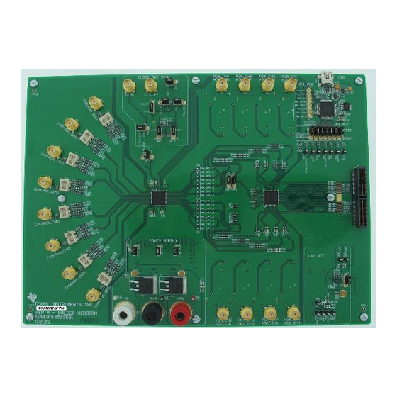
Page 65: Pga5807A Evm Top Side
PGA5807A EVM Layout www.ti.com Figure 81. PGA5807A EVM Top Side SLAU538 – October 2013 PGA5807A, 8-Channel, High-Bandwidth, Analog Front-End Evaluation Module Submit Documentation Feedback Copyright © 2013, Texas Instruments Incorporated... -
Page 66: Pga5807A Evm Ground Plane
PGA5807A EVM Layout www.ti.com Figure 82. PGA5807A EVM Ground Plane 1 PGA5807A, 8-Channel, High-Bandwidth, Analog Front-End Evaluation Module SLAU538 – October 2013 Submit Documentation Feedback Copyright © 2013, Texas Instruments Incorporated... -
Page 67: Pga5807A Evm Power Split Plane
PGA5807A EVM Layout www.ti.com Figure 83. PGA5807A EVM Power Split Plane 1 SLAU538 – October 2013 PGA5807A, 8-Channel, High-Bandwidth, Analog Front-End Evaluation Module Submit Documentation Feedback Copyright © 2013, Texas Instruments Incorporated... -
Page 68: Pga5807A Evm Power Split Plane
PGA5807A EVM Layout www.ti.com Figure 84. PGA5807A EVM Power Split Plane 2 PGA5807A, 8-Channel, High-Bandwidth, Analog Front-End Evaluation Module SLAU538 – October 2013 Submit Documentation Feedback Copyright © 2013, Texas Instruments Incorporated... -
Page 69: Pga5807A Evm Gnd Split Plane
PGA5807A EVM Layout www.ti.com Figure 85. PGA5807A EVM GND Split Plane 2 SLAU538 – October 2013 PGA5807A, 8-Channel, High-Bandwidth, Analog Front-End Evaluation Module Submit Documentation Feedback Copyright © 2013, Texas Instruments Incorporated... -
Page 70: Pga5807A Evm Bottom Side
PGA5807A EVM Layout www.ti.com Figure 86. PGA5807A EVM Bottom Side PGA5807A, 8-Channel, High-Bandwidth, Analog Front-End Evaluation Module SLAU538 – October 2013 Submit Documentation Feedback Copyright © 2013, Texas Instruments Incorporated... - Page 71 Any exceptions to this are strictly prohibited and unauthorized by Texas Instruments unless user has obtained appropriate experimental/development licenses from local regulatory authorities, which is responsibility of user including its acceptable authorization.
- Page 72 FCC Interference Statement for Class B EVM devices This equipment has been tested and found to comply with the limits for a Class B digital device, pursuant to part 15 of the FCC Rules. These limits are designed to provide reasonable protection against harmful interference in a residential installation. This equipment generates, uses and can radiate radio frequency energy and, if not installed and used in accordance with the instructions, may cause harmful interference to radio communications.
- Page 73 Also, please do not transfer this product, unless you give the same notice above to the transferee. Please note that if you could not follow the instructions above, you will be subject to penalties of Radio Law of Japan. Texas Instruments Japan Limited (address) 24-1, Nishi-Shinjuku 6 chome, Shinjuku-ku, Tokyo, Japan http://www.tij.co.jp...
- Page 74 FDA Class III or similar classification, then you must specifically notify TI of such intent and enter into a separate Assurance and Indemnity Agreement. Mailing Address: Texas Instruments, Post Office Box 655303, Dallas, Texas 75265 Copyright © 2013, Texas Instruments Incorporated...
- Page 75 IMPORTANT NOTICE Texas Instruments Incorporated and its subsidiaries (TI) reserve the right to make corrections, enhancements, improvements and other changes to its semiconductor products and services per JESD46, latest issue, and to discontinue any product or service per JESD48, latest issue.
Need help?
Do you have a question about the PGA5807A and is the answer not in the manual?
Questions and answers