Advertisement
Quick Links
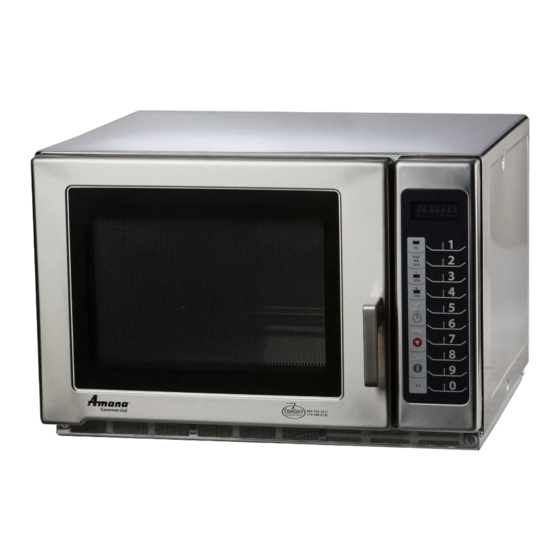
Commercial Microwave—Technical Information
208 / 240 V, 60 Hz Models
RFS18TS
P2001003M
MFS18TSSA
P2001009M
• Due to possibility of personal injury or property damage, always contact an authorized technician for servicing or
repair of this unit.
• Refer to Service Manual for installation, operating, testing, troubleshooting, and disassembly instruction.
All safety information must be followed as provided in Service Manual.
To avoid the risk of electrical shock, personal injury or death, disconnect power to oven and discharge capacitor
before servicing, unless testing requires it.
Power Source
Voltage AC
Amperage (Single Unit)
Frequency
Single Phase, 3 wire grounded
Receptacle
Plug
Power Output
Nominal microwave energy (IEC705)
Minimum temperature rise ( T)
Operating Frequency
Power Consumption
Cook Condition Microwave
Dimensions
Cabinet
Width
Height
Depth
Oven Interior
Width
Height
Depth
Weight
Crated
Uncrated
October 2013
©2013 ACP, Inc.
!
!
Models
MFS18TS
CAUTION
WARNING
RFS18TS MFS18TS
208 / 240 VAC
20 A
60 Hz
X
6-20R
6-20P
1800 Watts
18ºF / 7.7ºC
2450 MHz
3000 Watts / 15.3 Amps
21 3/4"
55 cm
14 1/4"
36.2 cm
20 1/4"
51.4 cm
14 1/4"
36.2 cm
9"
22.6 cm
16 3/8"
41.6 cm
73 lbs.
33 kg
67 lbs.
30 kg
1
P2001008M
MFS18TSSA
208 / 240 VAC
20 A
60 Hz
X
BS1363/A
BS1363/A
1800 Watts
18ºF / 7.7ºC
2450 MHz
3000 Watts / 13 Amps
21 3/4"
55 cm
14 1/4"
36.2 cm
20 1/4"
51.4 cm
14 1/4"
36.2 cm
9"
22.6 cm
16 3/8"
41.6 cm
73 lbs.
33 kg
67 lbs.
30 kg
16500024
Advertisement

Related Manuals for ACP RFS18TS


Summary of Contents for ACP RFS18TS
- Page 1 All safety information must be followed as provided in Service Manual. WARNING To avoid the risk of electrical shock, personal injury or death, disconnect power to oven and discharge capacitor before servicing, unless testing requires it. Models RFS18TS MFS18TS MFS18TSSA Power Source Voltage AC 208 / 240 VAC...
-
Page 2: Component Testing Procedures
Power In terminals ........ 240 VAC Power Out terminals......240 VAC If no power in, check power outlet. If no power out, check fuses. Circuit Protector Measure resistance across terminals ..Between Terminals: Less than 1 Ω 16500024 October 2013 ©2013 ACP, Inc. - Page 3 Press Pad 0 ..........Exit Service Test Mode Stop/Reset Pad ........... Error codes: E-08 ............Replace Control Board E-09 ............Replace Control Board Shorted or Open Keypad – Test E-10 ............and replace if necessary October 2013 16500024 ©2013 ACP, Inc.
- Page 4 DEFROST (20%) 2 & 10 Continuity MEDIUM (50%) 3 & 10 Continuity MED-HI (70%) 4 & 10 Continuity TIME ENTRY 5 & 10 Continuity STOP/RESET 6 & 10 Continuity START 7 & 10 Continuity 16500024 October 2013 ©2013 ACP, Inc.
- Page 5 208 / 240 VAC Ready ....Volts Relay 3 – Pin 1 to Pin 2 ......208 / 240 VAC Cook ....Volts Relay 3 – Pin 1 to Pin 2 ......0 VAC October 2013 16500024 ©2013 ACP, Inc.
- Page 6 17 ....1700 25 ....2500 9.5 .... 1700 13.5 ..2500 18 ....1800 27 ....2700 10 ..... 1800 15 .... 2700 19 ....1900 30 ....3000 10.5 ..1900 16.5 ..3000 16500024 October 2013 ©2013 ACP, Inc.
-
Page 7: Wiring And Schematic Diagrams
To avoid risk of electrical shock, personal injury or death, disconnect power to oven and discharge capacitor before servicing, unless testing requires it. NOTE: 1.DOOR IS OPENED. 2.WIRE COLOR SYMBOL COLOR BROWN WHITE BLACK BLUE YELLOW PINK GREEN DANGER HIGH VOLTAGE October 2013 16500024 ©2013 ACP, Inc.