Table of Contents
Advertisement
Quick Links
Wine Coolers
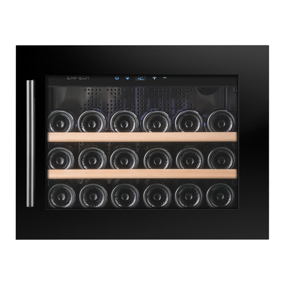
USER MANUAL
OSLO SERIES
ELEGANCE SERIES
COPENHAGEN SERIES
This manual contains important information including safety and
installation instructions of the appliances. Please read it carefully before
use and follow all safety information & instructions. It is recommended
to keep this manual for easy reference so that you can be familiar with the
operation of the appliance.
V1/2021
Advertisement
Table of Contents


Need help?
Do you have a question about the OSLO Series and is the answer not in the manual?
Questions and answers