
Related Manuals for IBASE Technology IB811F Series


Summary of Contents for IBASE Technology IB811F Series
- Page 1 IB811F Series ® ® ® Intel Pentium / Celeron Atom™ x7 / x5 SoC 3.5” Disk-Size SBC User’s Manual Version 2.0 (Sep. 2019)
- Page 2 No part of this publication may be reproduced, copied, stored in a retrieval system, translated into any language or transmitted in any form or by any means, electronic, mechanical, photocopying, or otherwise, without the prior written consent of IBASE Technology, Inc. (hereinafter referred to as “IBASE”). Disclaimer IBASE reserves the right to make changes and improvements to the products described in this document without prior notice.
-
Page 3: Compliance
0.1% by weight (1000 ppm) except for cadmium, limited to 0.01% by weight (100 ppm). • Lead (Pb) • Mercury (Hg) • Cadmium (Cd) • Hexavalent chromium (Cr6+) • Polybrominated biphenyls (PBB) • Polybrominated diphenyl ether (PBDE) IB811F Series User’s Manual... -
Page 4: Important Safety Information
Danger of explosion if the internal lithium-ion battery is replaced by an incorrect type. Replace only with the same or equivalent type recommended by the manufacturer. Dispose of used batteries according to the manufacturer’s instructions or recycle them at a local recycling facility or battery collection point. IB811F Series User’s Manual... -
Page 5: Warranty Policy
Software in use (such as OS and application software, including the version numbers) If repair service is required, you can download the RMA form at http://www.ibase.com.tw/english/Supports/RMAService/. Fill out the form and contact your distributor or sales representative. IB811F Series User’s Manual... -
Page 6: Table Of Contents
Connector (CN1) ............20 2.5.2 SATA III Connector (CN2, CN3) .......... 21 2.5.3 LAN Ports (CN4) ..............21 2.5.4 USB 3.0 Ports (CN5, CN6) ..........21 2.5.5 Console COM1 (RJ50) RS-232/422/485 Port (CN7) .... 22 IB811F Series User’s Manual... - Page 7 Fintek Super IO Configuration ..........53 4.4.5 Fintek Super IO Hardware Monitor ........55 4.4.6 M.2 Setup ................56 4.4.7 CPU Configuration ..............57 4.4.8 AMI Graphic Output Protocol Policy ........58 4.4.9 Network Stack Configuration ..........59 4.4.10 CSM Configuration ...............60 4.4.11 USB Configuration ..............61 IB811F Series User’s Manual...
- Page 8 Chipset Settings ................62 Security Settings ................67 Boot Settings ..................71 Save & Exit Settings ................72 Appendix ..................73 I/O Port Address Map ................ 74 Interrupt Request Lines (IRQ) ............77 Watchdog Timer Configuration ............79 IB811F Series User’s Manual viii...
-
Page 9: Chapter 1 General Information
Chapter 1 General Information The information provided in this chapter includes: • Features • Packing List • Block Diagram • Specifications • Board Overview • Board Dimensions... -
Page 10: Introduction
2 x GbE LAN, 4 x USB 3.0, 2 x USB 2.0, 4 x COM, 2 x SATA III, 1 x Mini PCIe slot (full-size), 1 x M.2 (B-key) • Configurable watchdog timer and digital I/O, mSATA, EuP/ErP • Wide temperature supported by IB811F-I50 and IB811F-I40 and IB811F-I30 IB811F Series User’s Manual... -
Page 11: Packing List
Cable Kit (IB76A) (including: SATA cable (SATA-53) Power cable (PW87) COM ports cable (PK1H) USB cable (USB29) • Heatsink for IB811F-I50/IB811F-I40/IB811F-I30 (HSIB811-A) • Heatsink for IB811F-420 / IB811F-335 (HSIB811-B) • Audio cable (Audio-18) • COM1 RJ50 cable (PK105) IB811F Series User’s Manual... -
Page 12: Specifications
Audio Codec & Controller Realtek ALC283QHD codec with speaker amplifier Power 9~36V DC-In (jumper-selectable ATX / AT power mode) Requirement Watchdog Yes (256 segments, 0, 1, 2…255 sec / min) Timer BIOS AMI BIOS H/W Monitor IB811F Series User’s Manual... - Page 13 On-board audio connector for Line-In, Line-Out, and Audio Mic-In Digital IO 4-In & 4-Out • 1 x Mini PCIe slot (full-size) with USB and mSATA Expansion • 1 x M.2 (B key) 3042 Slot with PCIe (x1), USB and Slots SATA IB811F Series User’s Manual...
- Page 14 • Storage: -40 ~ 110 °C • Storage: -40 ~ 110 ° (-40 ~ 230 °F) C (-40 ~ 230 °F) Relative 0 ~ 90 %, non-condensing at 60 °C Humidity All specifications are subject to change without prior notice. IB811F Series User’s Manual...
-
Page 15: Block Diagram
General Information Block Diagram IB811F Series User’s Manual... -
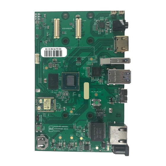
Page 16: Overview
Overview Top View Bottom View Photo of IB811F-420 *The photos above are for reference only. Some minor components may differ. IB811F Series User’s Manual... - Page 17 General Information I/O View Name Name COM1 (RJ50) Port LAN Port DisplayPort USB 3.0 Port HDMI Port IB811F Series User’s Manual...
-
Page 18: Dimensions
Dimensions 102.22 97.23 41.78 13.45 16.34 13.30 IB811F Series User’s Manual... -
Page 19: Chapter 2 Hardware Configuration
Chapter 2 Hardware Configuration This section provides information on jumper settings and connectors on the IB811F in order to set up a workable system. On top of that, you will also need to install crucial pieces such as the CPU and the memory before using the product. The topics covered are: •... -
Page 20: Essential Installations Before You Begin
Gently push the module in an upright position until the clips of the slot close to hold the module in place when the module touches the bottom of the slot. To remove the module, press the clips outwards with both hands, and the module will pop-up. IB811F Series User’s Manual... -
Page 21: Setting The Jumpers
When two pins of a jumper are encased in a jumper cap, this jumper is closed, i.e. turned On. When a jumper cap is removed from two jumper pins, this jumper is open, i.e. turned Off. IB811F Series User’s Manual... -
Page 22: Jumper & Connector Locations
Jumper & Connector Locations 10 9 9 10 9 10 BAT1 Atom™ QC/DC ® Intel Intel ® Pentium ® ® ® Intel Celeron Board diagram of IB811F IB811F Series User’s Manual... -
Page 23: Jumpers Quick Reference
LVDS Planel Power Selection eDP Panel Power Selection eDP / LVDS Panel Seelction ATX / AT Power Selection CMOS Data Clearance ME Register Clearance Factory Use Only 2.4.1 LVDS Panel Brightness Selection (JP1) Function Pin closed Illustration 3.3V (default) IB811F Series User’s Manual... -
Page 24: Lvds Panel Power Selection (Jp2)
2.4.2 LVDS Panel Power Selection (JP2) Function Pin closed Illustration 3.3V (default) 2.4.3 eDP Panel Power Selection (JP3) Function Pin closed Illustration 3.3V (default) IB811F Series User’s Manual... -
Page 25: Edp / Lvds Panel Selection (Jp4)
Hardware Configuration 2.4.4 eDP / LVDS Panel Selection (JP4) Function Pin closed Illustration LVDS (default) 2.4.5 ATX / AT Power Selection (JP5) Function Pin closed Illustration (default) IB811F Series User’s Manual... -
Page 26: Cmos Data Clearance (Jp6)
2.4.6 CMOS Data Clearance (JP6) Function Pin closed Illustration Normal (default) Clear CMOS 2.4.7 ME Register Clearance (JP7) Function Pin closed Illustration Normal (default) Clear ME IB811F Series User’s Manual... -
Page 27: Connectors Quick Reference
Mini PCIe / mSATA Slot COM2 / COM3 / COM4 RS-232 J16, J17, J12 Port M.2 (B key) 3042 Slot Front Panel Connector Digital I/O Connector DC Power Input Connector Factory Use Only J15, J20, J21 IB811F Series User’s Manual... -
Page 28: Edp Connector (Cn1)
2.5.1 eDP Connector (CN1) Assignment Assignment Ground BL_Power BL_Power Panel_VDD BL_Power Panel_VDD BL_Power Ground AUX_N AUX_P BRIGHTNESS Ground Bklt_en TX0_P Ground TX0_N Ground Ground Ground TX1_P Ground TX1_N Ground Ground IB811F Series User’s Manual... -
Page 29: Sata Iii Connector (Cn2, Cn3)
Hardware Configuration 2.5.2 SATA III Connector (CN2, CN3) CN2: shared with M.2 B-key CN3: shared with mSATA 2.5.3 LAN Ports (CN4) 2.5.4 USB 3.0 Ports (CN5, CN6) IB811F Series User’s Manual... -
Page 30: Console Com1 (Rj50) Rs-232/422/485 Port (Cn7)
DCD, Data carrier detect Ground DTR, Data terminal ready Ground CTS, Clear to send TX, Transmit RTS, Request to send RX, Receive RI, Ring Indicator Assignment RS-232 RS-422 RS-485 Ground Ground Ground Ground Ground Ground Data+ Data- IB811F Series User’s Manual... -
Page 31: Displayport (Cn8)
Hardware Configuration 2.5.6 DisplayPort (CN8) 2.5.7 HDMI Port (CN9) 2.5.8 LCD Backlight Connector (J2) Assignment Assignment +12V Brightness Control Backlight Enable Ground IB811F Series User’s Manual... -
Page 32: Lvds Connector (J1, J3)
2.5.9 LVDS Connector (J1, J3) J3: 1 channel J1: 2 channel Assignment Assignment TX0P TX0N Ground Ground TX1P TX1N Ground Ground TX2P TX2N Ground Ground CLKP CLKN Ground Ground TX3P TX3N IB811F Series User’s Manual... -
Page 33: Audio Connector (J4)
Hardware Configuration 2.5.10 Audio Connector (J4) Assignment Assignment Lineout_L Lineout_R JD_FRONT Ground LINEIN_L Linein_R JD_LINEIN Ground MIC_L MIC-R JD_MIC1 Ground 2.5.11 DDR3L SO-DIMM Slot (J5, J8) IB811F Series User’s Manual... -
Page 34: Usb 2.0 Connector (J6)
2.5.12 USB 2.0 Connector (J6) Assignment Assignment Ground Ground 2.5.13 Amplifier Connector (J7) Assignment Assignment OUTL+ OUTR- OUTL- OUTR+ IB811F Series User’s Manual... -
Page 35: Sata Hdd Power Connector (J10)
Hardware Configuration 2.5.14 SATA HDD Power Connector (J10) Assignment Assignment Ground Ground +12V 2.5.15 Mini PCIe / mSATA Slot (J11) IB811F Series User’s Manual... -
Page 36: Com2 / Com3 / Com4 Rs-232 Port (J16, J17, J12)
DCD, Data carrier detect RXD, Receive data TXD, Transmit data DTR, Data terminal ready Ground DSR, Data set ready RTS, Request to send CTS, Clear to send RI, Ring indicator Not Used 2.5.17 M.2 (B key) 3042 Slot (J14) IB811F Series User’s Manual... -
Page 37: Front Panel Connector (J13)
Orientation is not required when making a connection to this header. • Power LED: Pins 7 and 8 This connector connects to the system power LED on control panel. This LED will light when the system turns on. IB811F Series User’s Manual... -
Page 38: Digital I/O Connector (J18)
2.5.19 Digital I/O Connector (J18) Assignment Assignment Ground OUT3 OUT1 OUT2 OUT0 2.5.20 DC Power Input Connector (J19) Assignment +9V ~ +36V Ground IB811F Series User’s Manual... -
Page 39: Chapter 3 Drivers Installation
Chapter 3 Drivers Installation This chapter introduces installation of the following drivers: • ® Intel Chipset Software Installation Utility • VGA Driver • HD Audio Driver • ® Intel Trusted Execution Engine Installation • LAN Driver... -
Page 40: Introduction
The contents of this section include the following: Note: After installing your Windows operating system, you must install the ® Intel Chipset Software Installation Utility first before proceeding with the drivers installation. IB811F Series User’s Manual... -
Page 41: Intel ® Chipset Software Installation Utility
Follow the instructions below to complete the installation. Insert the disk enclosed in the package with the board. Click Intel on the left pane and then Intel(R) Apollolake Chipset Drivers on the right pane. Click Intel(R) Chipset Software Installation Utility. IB811F Series User’s Manual... - Page 42 Click Yes to accept the software license agreement and proceed with the installation process. On the Readme File Information screen, click Install for installation. The driver has been completely installed. You are suggested to restart the computer for changes to take effect. IB811F Series User’s Manual...
-
Page 43: Vga Driver Installation
Driver Installation VGA Driver Installation Click Intel on the left pane and then Intel(R) Apollolake Chipset Drivers on the right pane. Click Intel(R) Apollolake Graphics Driver. IB811F Series User’s Manual... - Page 44 When the Welcome screen appears, click Next to continue. Click Yes to accept the license agreement and click Next until the installation starts. The driver has been completely installed. You are suggested to restart the computer for changes to take effect. IB811F Series User’s Manual...
-
Page 45: Hd Audio Driver Installation
Driver Installation HD Audio Driver Installation Click Intel on the left pane and then Intel(R) Apollolake Chipset Drivers on the right pane. Click Realtek High Definition Audio Driver. IB811F Series User’s Manual... - Page 46 On the Welcome screen of the InstallShield Wizard, click Next for installation. Click Next until the installation starts. The driver has been completely installed. You are suggested to restart the computer for changes to take effect. IB811F Series User’s Manual...
-
Page 47: Intel ® Trusted Execution Engine Drivers
Driver Installation ® Intel Trusted Execution Engine Drivers Click Intel on the left pane and then Intel(R) Apollolake Chipset Drivers on the right pane. Click Intel(R) TXE Drivers. IB811F Series User’s Manual... - Page 48 When the Welcome screen appears, click Next. Accept the license agreement and click Next. Click Next for installation. As the driver has been sccessfully installed, you are suggested to restart the computer for changes to take effect. IB811F Series User’s Manual...
-
Page 49: Intel ® Serial Io Drivers
Driver Installation ® Intel Serial IO Drivers Click Intel on the left pane and then Intel(R) Apollolake Chipset Drivers on the right pane. Click Intel(R) Serial IO Drivers. IB811F Series User’s Manual... - Page 50 Accept the license agreement and click Next. After reading the Readme File Information, click Next for installation. As the driver has been sccessfully installed, you are suggested to restart the computer for changes to take effect. IB811F Series User’s Manual...
-
Page 51: Lan Driver Installation
Driver Installation LAN Driver Installation Click LAN Card on the left pane and then Intel LAN Controller Drivers on the right pane. Click Intel(R) I21x Gigabit Network Drivers.. IB811F Series User’s Manual... - Page 52 On the Setup Options screen, click the checkbox to select the desired driver(s) for installation. Then click Next to continue. The wizard is ready for installation. Click Install. As the installation is complete, you are suggested to restart the computer for changes to take effect. IB811F Series User’s Manual...
-
Page 53: Chapter 4 Bios Setup
Chapter 4 BIOS Setup This chapter describes the different settings available in the AMI BIOS that comes with the board. The topics covered in this chapter are as follows: • Main Settings • Advanced Settings • Chipset Settings • Boot Settings •... -
Page 54: Introduction
The following message will appear on the screen: Press <DEL> Enter Setup In general, press the arrow keys to highlight items, <Enter> to select, the <PgUp> and <PgDn> keys to change entries, <F1> for help, and <Esc> to quit. IB811F Series User’s Manual... - Page 55 These defaults have been carefully chosen by both AMI and your system manufacturer to provide the absolute maximum performance and reliability. Changing the defaults could make the system unstable and crash in some cases. IB811F Series User’s Manual...
-
Page 56: 4.3 Main Settings
4.3 Main Settings BIOS Setting Description System Date Sets the date. Use the <Tab> key to switch between the data elements. System Time Set the time. Use the <Tab> key to switch between the data elements. IB811F Series User’s Manual... -
Page 57: 4.4 Advanced Settings
BIOS Setup 4.4 Advanced Settings This section allows you to configure, improve your system and allows you to set up some system features according to your preference. IB811F Series User’s Manual... - Page 58 TPM 1.2 will restrict support to TPM 1.2 devices. TPM 2.0 will restrict support to TPM 2.0 devices. Auto will support both with the default sat to TPM 2.0 devices if not found. TPM 1.2 devices will be enumerated. IB811F Series User’s Manual...
- Page 59 Enables / Disables the system ability to hibernate (OS/S4 Sleep State). This option may be not effective with some OS. ACPI Sleep State Selects an ACPI sleep state (Suspend Disabled or S3) where the system will enter when the Suspend button is pressed. IB811F Series User’s Manual...
-
Page 60: Lvds (Edp/Dp) Configuration
Options: 800 x 600 / 1024 x 768 / 1280 x 1024 / 1366 x 768 / 1440 x 900 / 1600 x 900 / 1920 x 1080 LVDS Backlight Level Selects from Level 1 to Level 8 for the LVDS Control backlight. IB811F Series User’s Manual... -
Page 61: Fintek Super Io Configuration
Options: All Enable / Enable Ethernet for WOL / All Disable Serial Ports Sets parameters of serial ports. Configuration Enables / Disables the serial port and select an optimal setting for the Super IO device. IB811F Series User’s Manual... - Page 62 IO = 2E8h; IRQ = 3, 4, 5, 6, 7, 9, 10, 11, 12 Device Mode Changes the serial port mode to: • RS232 • RS485 TX Low Active • RS485 with Termination TX Low Active • RS422 • RS422 with Termination IB811F Series User’s Manual...
-
Page 63: Fintek Super Io Hardware Monitor
PC health status. CPU Shutdown Sets a threshold of temperature to shut down if Temperature CPU goes overheated. Options: Disabled / 70 °C / 75 °C / 80 °C / 85 °C / 90 °C / 95 °C IB811F Series User’s Manual... -
Page 64: Setup
4.4.6 M.2 Setup BIOS Setting Description M.2 Select Selects the M.2 interface as SATA or PCIe. IB811F Series User’s Manual... -
Page 65: Cpu Configuration
Displays the socket specific CPU information. Information CPU Power Allows you to enable / disable Turbo Mode. Management Active Processor Enables / Disables the cores in the processor Cores package. Monitor Mwait Enables / Disables Monitor Mwait. IB811F Series User’s Manual... -
Page 66: Ami Graphic Output Protocol Policy
4.4.8 AMI Graphic Output Protocol Policy BIOS Setting Description Output Select Outputs through HDMI interface. IB811F Series User’s Manual... -
Page 67: Network Stack Configuration
If disabled, Ipv4 HTTP boot option will not be created. PXE boot wait time Assigns a period of time to press ESC key to abort the PXE boot. Media detect count Assigns a number of times to check the presence of media. IB811F Series User’s Manual... -
Page 68: Csm Configuration
Postponed executes the trap during legacy boot. Boot option filter Controls the priority of Legacy and UEFI ROMs. Option ROM Controls the execution of UEFI and Legacy PXE execution - Network Option ROM. Options: Do not launch/UEFI/ Legacy. IB811F Series User’s Manual... -
Page 69: Usb Configuration
The maximum time the device will take before it delay properly reports itself to the Host Controller. Auto uses default value for a Root port it is 100ms. But for a Hub port, the delay is taken from Hub descriptor. IB811F Series User’s Manual... -
Page 70: 4.5 Chipset Settings
4.5 Chipset Settings 4.5.1 South Cluster Configuration IB811F Series User’s Manual... - Page 71 BIOS Setup 4.5.1.1 HD Audio Configuration 4.5.1.2 PCI Express Configuration BIOS Setting Description PCI Express Root Accesses the control of the PCI Express Root Port 1 ~ 6 Port. IB811F Series User’s Manual...
- Page 72 Options: Disable / L0s / L1 / L0SL1 / Auto L1 Substates Sets PCIe L1 substates. Options: Disables / L1.1 / L1.2 / L1.1 & L1.2 PME SCI Enables / Disables PME SCI. PCIe Speed Configures the PCIe speed. IB811F Series User’s Manual...
- Page 73 BIOS Setting Description Chipset SATA Enables / Disables the Chipset SATA Controller. The Chipset SATA Controller supports the 2 black internal SATA ports (up to 3Gb/s supported per port). SATA Mode Selection Determines how SATA controller(s) operate. IB811F Series User’s Manual...
- Page 74 USB port from reporting a device connection to the controller. XDCI Support Enables / Disables XDCI. XHCI Disable FALSE makes the XHCI Link Compliance Mode Compliance Mode not disabled. TRUE disables the XHCI Link Compliance Mode. IB811F Series User’s Manual...
-
Page 75: 4.6 Security Settings
BIOS Setup 4.6 Security Settings BIOS Setting Description Setup Administrator Sets an administrator password for the setup Password utility. User Password Sets a user password. Secure Boot Customizable Secure Boot IB811F Series User’s Manual... - Page 76 And after reset, the mode will return to STANDARD mode. Restore Factory Keys Force System to User Mode. Configure NVRAM to contain OEM-defined factory default Secure Boot keys. Key Management Enables expert users to modify Secure Boot Policy variables without full authentication IB811F Series User’s Manual...
- Page 77 (PK). Options available: Update Key Exchange Keys Displays the current status of the Key Exchange Key Database (KEK). Options available: Update/Append. Authorized Signatures Displays the current status of the Authorized Signature Database. Options available: Update /Append. IB811F Series User’s Manual...
- Page 78 Signatures Database. Options available: Update /Append. Authorized Displays the current status of the Authorized TimeStamps TimeStamps Database. Options available: Update /Append. OsRecovery Displays the current status of the OsRecovery Signatures Signature Database. Options available: Update /Append. IB811F Series User’s Manual...
-
Page 79: 4.7 Boot Settings
Boot mode select Selects a Boot mode, Legacy / UEFI / Dual. Fixed Boot Order Sets the system boot order priorities for hard disk, Priorities CD/DVD, USB hard disk, USB CD/DVD, USB Key, USB Floppy, USB Lan, Network. IB811F Series User’s Manual... -
Page 80: 4.8 Save & Exit Settings
Restores / Loads defaults values for all the setup Restore Defaults options. Save as User Defaults Saves the changes done so far as User Defaults. Restores the user defaults to all the setup Restore User Defaults options. IB811F Series User’s Manual... -
Page 81: Appendix
Appendix This section provides the mapping addresses of peripheral devices and the sample code of watchdog timer configuration. -
Page 82: I/O Port Address Map
Motherboard resources 0x000000B2-0x000000B3 Motherboard resources 0x00000680-0x0000069F Motherboard resources 0x00000400-0x0000047F Motherboard resources 0x00000500-0x000005FE Motherboard resources 0x00000600-0x0000061F Motherboard resources 0x0000164E-0x0000164F Motherboard resources 0x0000F040-0x0000F05F Intel(R) Celeron(R)/Pentium(R) Processor SMBUS - 5AD4 0x0000D000-0x0000DFFF Intel(R) Celeron(R)/Pentium(R) Processor PCI Express Root Port - 5AD9 IB811F Series User’s Manual... - Page 83 0x000000A4-0x000000A5 Programmable interrupt controller 0x000000A8-0x000000A9 Programmable interrupt controller 0x000000AC-0x000000AD Programmable interrupt controller 0x000000B0-0x000000B1 Programmable interrupt controller 0x000000B4-0x000000B5 Programmable interrupt controller 0x000000B8-0x000000B9 Programmable interrupt controller 0x000000BC-0x000000BD Programmable interrupt controller 0x000004D0-0x000004D1 Programmable interrupt controller 0x0000F000-0x0000F03F Intel(R) HD Graphics IB811F Series User’s Manual...
- Page 84 Address Device Description 0x0000F090-0x0000F097 Standard SATA AHCI Controller 0x0000F080-0x0000F083 Standard SATA AHCI Controller 0x0000F060-0x0000F07F Standard SATA AHCI Controller 0x00000040-0x00000043 System timer 0x00000050-0x00000053 System timer IB811F Series User’s Manual...
-
Page 85: Interrupt Request Lines (Irq)
Controller IRQ 39 SDA Standard Compliant SD Host Controller IRQ 54 ~ IRQ 204 Microsoft ACPI-Compliant System IRQ 256 ~ IRQ 511 Microsoft ACPI-Compliant System IRQ 4294967279 Intel(R) USB 3.0 eXtensible Host Controller - 1.0 (Microsoft) IB811F Series User’s Manual... - Page 86 Intel(R) I211 Gigabit Network Connection #2 IRQ 4294967285 IRQ 4294967286 ~ Intel(R) I211 Gigabit Network Connection IRQ 4294967291 IRQ 4294967292 Intel(R) Trusted Execution Engine Interface IRQ 4294967293 Intel(R) HD Graphics IRQ 4294967294 Standard SATA AHCI Controller IB811F Series User’s Manual...
-
Page 87: Watchdog Timer Configuration
**endptr; char SIO; printf("Fintek 81964 watch dog program\n"); SIO = Init_F81964(); if (SIO == 0) printf("Can not detect Fintek 81964, program abort.\n"); return(1); }//if (SIO == 0) if (argc != 2) printf(" Parameter incorrect!!\n"); return (1); IB811F Series User’s Manual... - Page 88 DisableWDT(void) unsigned char bBuf; Set_F81964_LD(0x07); //switch to logic device 7 bBuf = Get_F81964_Reg(0xFA); bBuf &= ~0x01; Set_F81964_Reg(0xFA, bBuf); //disable WDTO output bBuf = Get_F81964_Reg(0xF5); bBuf &= ~0x20; bBuf |= 0x40; Set_F81964_Reg(0xF5, bBuf); //disable WDT //--------------------------------------------------------------------------- //--------------------------------------------------------------------------- IB811F Series User’s Manual...
- Page 89 Init_Finish; F81964_BASE = 0x00; result = F81964_BASE; Init_Finish: return (result); //--------------------------------------------------------------------------- void Unlock_F81964 (void) outportb(F81964_INDEX_PORT, F81964_UNLOCK); outportb(F81964_INDEX_PORT, F81964_UNLOCK); //--------------------------------------------------------------------------- void Lock_F81964 (void) outportb(F81964_INDEX_PORT, F81964_LOCK); //--------------------------------------------------------------------------- void Set_F81964_LD( unsigned char LD) Unlock_F81964(); outportb(F81964_INDEX_PORT, F81964_REG_LD); outportb(F81964_DATA_PORT, LD); Lock_F81964(); IB811F Series User’s Manual...
- Page 90 F81964_DATA_PORT (F81964_BASE+1) //--------------------------------------------------------------------------- #define F81964_REG_LD 0x07 //--------------------------------------------------------------------------- #define F81964_UNLOCK 0x87 #define F81964_LOCK 0xAA //--------------------------------------------------------------------------- unsigned int Init_F81964(void); void Set_F81964_LD( unsigned char); void Set_F81964_Reg( unsigned char, unsigned char); unsigned char Get_F81964_Reg( unsigned char); //--------------------------------------------------------------------------- #endif // F81964_H IB811F Series User’s Manual...
Need help?
Do you have a question about the IB811F Series and is the answer not in the manual?
Questions and answers