
Related Manuals for IBASE Technology IB953 Series


Summary of Contents for IBASE Technology IB953 Series
- Page 1 IB953 Series ® 11th Generation Intel ® Core™ i7/i5/i3/ Celeron 3.5" Disk-Size SBC User’s Manual Version 1.0 (April 2021)
- Page 2 No part of this publication may be reproduced, copied, stored in a retrieval system, translated into any language or transmitted in any form or by any means, electronic, mechanical, photocopying, or otherwise, without the prior written consent of IBASE Technology, Inc. (hereinafter referred to as “IBASE”). Disclaimer IBASE reserves the right to make changes and improvements to the products described in this document without prior notice.
- Page 3 0.1% by weight (1000 ppm) except for cadmium, limited to 0.01% by weight (100 ppm). • Lead (Pb) • Mercury (Hg) • Cadmium (Cd) • Hexavalent chromium (Cr6+) • Polybrominated biphenyls (PBB) • Polybrominated diphenyl ether (PBDE) IB953 Series User’s Manual...
- Page 4 Replace only with the same or equivalent type recommended by the manufacturer. Dispose of used batteries according to the manufacturer’s instructions or recycle them at a local recycling facility or battery collection point. IB953 Series User’s Manual...
- Page 5 Software in use (such as OS and application software, including the version numbers) If repair service is required, you can download the RMA form at http://www.ibase.com.tw/english/Supports/RMAService/. Fill out the form and contact your distributor or sales representative. IB953 Series User’s Manual...
-
Page 6: Table Of Contents
SATA Power Connector (J13) ..........26 2.5.10 Digital I/O Connector (J17) ........... 26 2.5.11 Front Panel Setting Connector (J18) ........27 2.5.12 COM2 Serial Ports (J19) ............. 28 2.5.13 CPU Fan Power Connector (CPU_FAN1) ......29 IB953 Series User’s Manual... - Page 7 Chipset Settings ................61 Security Settings ................65 Boot Settings ..................66 Save & Exit Settings ................67 Appendix ..................69 I/O Port Address Map ................70 Interrupt Request Lines (IRQ) ............72 Watchdog Timer Configuration ............73 Onboard Connector Reference Types ..........77 IB953 Series User’s Manual...
-
Page 9: Chapter 1 General Information
Chapter 1 General Information The information provided in this chapter includes: • Features • Packing List • Optional Accessories • Specifications • Block Diagram • Board Pictures • Board Dimensions... -
Page 10: Introduction
Introduction • IB953 series is a 3.5” disk-size single board computer based on the platform of 11th Gen Intel® Core™ i7/i5/i3/ Celeron® processor. It features two DDR4-3200 SO-DIMM sockets with 64GB capacity and interface for two DisplayPort, eDP and 24-bit dual-channel LVDS. Fast connection is provided by two USB 2.0, three USB 3.1, two SATA III,... -
Page 11: Packing List
IBASE provides optional accessories as follows. • Cable Kit (IB76A-2) Including: DC-In power cable (PW87) COM ports cable (PK1H) SATA & HDD power cable (SATA-53A) USB 2.0 cable (USB29) • Audio cable (Audio-18) • Heat spreader (HSIB953-1) • Heat sink (HSIB953-A) IB953 Series User’s Manual... -
Page 12: Specifications
12V ~ 24V DC-In (+/- 10%) Requirement Watchdog Yes (256 segments, 0, 1, 2…255 sec / min) Timer BIOS AMI BIOS H/W Monitor Dimensions 102.22 x 147.01 mm (4.02” x 5.8”) RoHS Certification CE, FCC Class B IB953 Series User’s Manual... - Page 13 • Operation: 0 ~ 60 °C (32 ~ 140 °F) Temperature • Storage: -20 ~ 80 °C (-4 ~ 176 °F) Relative 0 ~ 90 %, non-condensing at 60 °C Humidity All specifications are subject to change without prior notice. IB953 Series User’s Manual...
-
Page 14: Block Diagram
Block Diagram IB953 Series User’s Manual... -
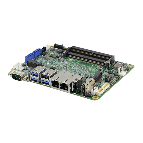
Page 15: Board Pictures
General Information Board Pictures Top View Bottom View *The photos above are for reference only. Some minor components may differ. IB953 Series User’s Manual... - Page 16 I/O View Connector Function COM1 Port USB 3.1 #1, #2 USB 3.1 #3, USB 2.0 #4 LAN Ports DP++ DP++ IB953 Series User’s Manual...
-
Page 17: Dimensions
General Information Dimensions IB953 Series User’s Manual... - Page 18 This page is intentionally left blank. IB953 Series User’s Manual...
-
Page 19: Chapter 2 Hardware Configuration
Chapter 2 Hardware Configuration This section provides information on jumper settings and connectors on the IB953 in order to set up a workable system. On top of that, you will also need to install crucial pieces such as the CPU and the memory before using the product. -
Page 20: Essential Installations
Essential Installations 2.1.1 Installing the Memory The IB953 series supports two DDR4 memory sockets. To install the modules, locate the memory slot on the board and perform the following steps: Align the key of the memory module with that on the memory slot and insert the module slantwise. -
Page 21: Setting The Jumpers
When two pins of a jumper are encased in a jumper cap, this jumper is closed, i.e. turned On. When a jumper cap is removed from two jumper pins, this jumper is open, i.e. turned Off. IB953 Series User’s Manual... -
Page 22: Jumper & Connector Locations
Jumper & Connector Locations Board diagram of IB953 IB953 Series User’s Manual... -
Page 23: Jumpers Quick Reference
Clear CMOS Data eDP Power Selection LVDS Power Selection AT/ATX Selection JP5 (For power) LVDS Panel Power / Brightness Selections JP7 (For brightness) 2.4.1 Clear RTC Data (JP1) Function Pin closed Setting Normal (default) Clear RTC IB953 Series User’s Manual... -
Page 24: Clear Cmos Data (Jp2)
2.4.2 Clear CMOS Data (JP2) Function Pin closed Setting Normal (default) Clear CMOS 2.4.3 eDP Power Selection (JP4) Function Pin closed Setting 3.3V (default) IB953 Series User’s Manual... -
Page 25: Lvds Power Selection (Jp5)
Hardware Configuration 2.4.4 LVDS Power Selection (JP5) Function Pin closed Setting 3.3V (default) 2.4.5 AT / ATX Selection (JP6) Function Pin closed Setting Open Close IB953 Series User’s Manual... -
Page 26: Lvds Panel Power / Brightness Selections (Jp5 / Jp7)
2.4.6 LVDS Panel Power / Brightness Selections (JP5 / JP7) JP5: JP3: Jumper Function Pin closed Setting 3.3V (default) 3.3V Open (default) Close IB953 Series User’s Manual... -
Page 27: Connectors Quick Reference
DP Connectors CN8, CN9 Audio Connector Audio AMP Connector USB2 #5 #6 LVDS CHB Connector (1st, 2nd) J14, J12 SATA Power Connector Digital I/O Connector Front Panel Setting Connector COM2 Serial Ports CPU Fan Power Connector CPU_FAN1 IB953 Series User’s Manual... -
Page 28: Sata Connectors (Cn1, Cn3)
2.5.1 SATA Connectors (CN1, CN3) Assignment Assignment Ground Ground Ground IB953 Series User’s Manual... -
Page 29: Edp Connector (Cn2)
Ground Ground +3.3V Ground EDP BKLT (+12V) Ground Hot Plug detect Ground Ground +5V (1A) TXN3 TXP3 Back Light Control Ground Back Light Enable TXN2 EDP BKLT (+12V) TXP2 +3.3V (1A) Ground Ground TXN1 TXP1 Ground IB953 Series User’s Manual... -
Page 30: Com1 Serial Port (Cn4)
2.5.3 COM1 Serial Port (CN4) Assignment RS-232 RS-422 RS-485 DATA- DATA+ Ground Ground Ground IB953 Series User’s Manual... -
Page 31: Dp Connectors (Cn8, Cn9)
Hardware Configuration 2.5.4 DP Connectors (CN8, CN9) Assignment Assignment LAN0_P LAN3_N LAN0_N CONFIG LAN1_P AUXP LAN1_N LAN2_P AUXN Hot Plug LAN2_N LAN3_P +5V(500mA) IB953 Series User’s Manual... -
Page 32: Audio Connector (J2)
2.5.5 Audio Connector (J2) Remarks: HK_DF11-12S-PA66H Assignment Assignment LINE OUT_L LINE OUT_R FRONT_JD LINE IN_L LINE IN_R LINE _JD MIC_L MIC_R MIC_JD 2.5.6 Audio AMP Connector (J4) Remarks: E-CALL_0110-161-040 Assignment SPK_L+ SPK_L- SPK_R- SPK_R+ IB953 Series User’s Manual... -
Page 33: Usb2 #5 #6 (J6)
+5V (500mA) USB_PN USB_PP USB_PP USB_PN +5V (500mA) 2.5.8 LVDS CHB Connector (J12 - 2 , J14 - 1 Remarks: HIROSE_DF20G-20DP-1V(56) Assignment Assignment TX0P TX0N TX1P TX1N TX2P TX2N CLKP CLKN TX3P TX3N +3.3V (1A) +3.3V IB953 Series User’s Manual... -
Page 34: Sata Power Connector (J13)
2.5.9 SATA Power Connector (J13) Remarks: E-CALL_0110-071-040 Assignment +5V (1A) +12V (1A) 2.5.10 Digital I/O Connector (J17) * 4 in, 4 out Remarks: E-CALL_0196-01-200-100 Assignment Assignment Ground Out3 Out1 Out2 Out0 IB953 Series User’s Manual... -
Page 35: Front Panel Setting Connector (J18)
Orientation is not required when making a connection to this header. • Power LED: Pins 7 and 8 This connector connects to the system power LED on control panel. This LED will light when the system turns on. IB953 Series User’s Manual... -
Page 36: Com2 Serial Ports (J19)
2.5.12 COM2 Serial Ports (J19) Remarks: HK_DF11-10S-PA66H Assignment RS-232 RS-422 RS-485 DATA- DATA+ Ground Ground Ground IB953 Series User’s Manual... -
Page 37: Cpu Fan Power Connector (Cpu_Fan1)
Hardware Configuration 2.5.13 CPU Fan Power Connector (CPU_FAN1) Remarks: PWM only Assignment Ground +12V (1A) Rotation detection Control IB953 Series User’s Manual... - Page 38 This page is intentionally left blank. IB953 Series User’s Manual...
-
Page 39: Chapter 3 Drivers Installation
Chapter 3 Drivers Installation This chapter introduces installation of the following drivers: ® • Intel Chipset Software Installation Utility • VGA Driver • HD Audio Driver • LAN Driver ® • Intel Management Engine Drivers Installation ® • Intel Thunderbolt Drivers Installation... -
Page 40: Introduction
INF files for Plug & Play function for Intel chipset components. Follow the instructions below to complete the installation. Insert the drivers disk in the disk drive. Click Intel on the left pane and then Intel(R) TigerLake-U Chipset Drivers on the right pane. IB953 Series User’s Manual... - Page 41 Chipset Device Software appears, click Next to continue. Accept the software license agreement and proceed with the installation process. On the Readme File Information screen, click Install. After completing the installation, click Finish to complete the setup process. IB953 Series User’s Manual...
-
Page 42: Vga Driver Installation
When the Welcome screen appears, click Next to continue. Click Yes to accept the license agreement. On the Readme File Information screen, click Next until the installation starts. When Setup is Complete, click Finish to restart the computer for changes to take effect. IB953 Series User’s Manual... -
Page 43: Hd Audio Driver Installation
Intel(R) TigerLake-U Chipset Drivers on the right pane. Click Realtek High Definition Audio Driver. On the Welcome screen of the InstallShield Wizard, click Next. Click Next until the installation starts. After the installation, restart the computer for changes to take effect. IB953 Series User’s Manual... -
Page 44: Lan Driver Installation
Insert the drivers disk in the disk drive. Click Intel on the left pane and then Intel(R) TigerLake-U Chipset Drivers on the right pane. Click Intel(R) PRO LAN Network Drivers.. On the Network Connections screen, click Install Drivers and Software. IB953 Series User’s Manual... - Page 45 On the Setup Options screen, click the checkbox to select the desired driver(s) for installation. Then click Next to continue. On the Ready to Install the Program screen, click Install to begin the installation. When the Install wizard hascompleted, click Finish. IB953 Series User’s Manual...
-
Page 46: Intel ® Management Engine Drivers Installation
Intel Management Engine Drivers Installation Insert the disk enclosed in the package with the board. Click Intel on the left pane and then Intel(R) TigerLake-U Chipset Drivers on the right pane. Click Intel(R) ME 12.x Drivers. IB953 Series User’s Manual... - Page 47 When the Welcome screen appears, click Next. Accept the license agreement and click Next. When the Destination Folder screen appears, click Next and the components will be installed. After Intel Management Engine Components have been successfully installed, click Finish. IB953 Series User’s Manual...
-
Page 48: Intel ® Thunderbolt Drivers Installation
® Intel Thunderbolt Drivers Installation Insert the disk enclosed in the package with the board. Click Intel on the left pane and then Intel(R) TigerLake-U Chipset Drivers on the right pane. Click Intel(R) Thunderbolt Drivers. IB953 Series User’s Manual... - Page 49 Driver Installation In the next screen, accept the license agreement and click Next. When the drivershave been successfully installed, click Restart. IB953 Series User’s Manual...
- Page 50 This page is intentionally left blank. IB953 Series User’s Manual...
-
Page 51: Chapter 4 Bios Setup
Chapter 4 BIOS Setup This chapter describes the different settings available in the AMI BIOS that comes with the board. The topics covered in this chapter are as follows: • Main Settings • Advanced Settings • Chipset Settings • Security Settings •... -
Page 52: Introduction
These defaults have been carefully chosen by both AMI and your system manufacturer to provide the absolute maximum performance and reliability. Changing the defaults could make the system unstable and crash in some cases. IB953 Series User’s Manual... -
Page 53: Main Settings
Sets the date. Use the <Tab> key to switch System Date between the data elements. Set the time. Use the <Tab> key to switch System Time between the data elements. NOTE: Below is the corresponding screen for the IB953EF BIOS IB953 Series User’s Manual... -
Page 54: Advanced Settings
4.4 Advanced Settings This section allows you to configure system features according to your preference. IB953 Series User’s Manual... - Page 55 Seiral IO UART0 needs to be enabled to select BT Discrete Bluetooth Module. Module Default: Disabled Advanced Configure ACPI objects for wireless devices Settings Default: Disabled WWAN Configure WWAN related options. Configuration WWAN Device: enable or disable M.2 WWAN device WWAN Reset Default: Enabled Workaround IB953 Series User’s Manual...
- Page 56 Enables utilization of additional hardware Execution Technology capabilities provided by Intel® Trusted Execution Technology. Changes require a full power cycle to take effect. NOTE: The selection for Hyper-Threading is available on IB953AF-i7, IB953AF-i5 and IB953EF-i3 only (not on IB953EF-CLE). IB953 Series User’s Manual...
- Page 57 BIOS Setting Description Allows more than two frequency ranges to be Intel Speedstep supported Enable/Disable Intel Speed Shift Technology Intel Speed Shift support. Enabling will expose the CPPC v2 interface Technology to allow for hardware controlled P-states. IB953 Series User’s Manual...
- Page 58 4.4.4 PCH-FW Configuration IB953 Series User’s Manual...
- Page 59 TPM 1.2 will restrict support to TPM 1.2 devices. TPM 2.0 will restrict support to TPM 2.0 devices. Device Select Auto will support both with the default set to TPM 2.0 devices if not found, TPM 1.2 devices will be enumerated. IB953 Series User’s Manual...
- Page 60 4.4.6 ACPI Settings BIOS Setting Description Enables / Disables the system ability to hibernate Enable Hibernation (OS/S4 Sleep State). This option may be not effective with some OS. IB953 Series User’s Manual...
- Page 61 960, 1280 x 1024, 1366 x 768, 1440 x 900, 1600 x 900, 1600 x 1200, 1680 x 1050, 1920 x 1080, 1920 x 1200 LVDS Brightness Options: 0(Min), 1, 2, 3, 4, 5, 6, 7(Max) Control IB953 Series User’s Manual...
- Page 62 Sets parameters of serial ports. Serial Ports Enables / Disables the serial port and select an Configuration optimal setting for the Super IO device. Standby Power on This feature is available in IB953EF but not in S5(ERP) IB953AF. IB953 Series User’s Manual...
- Page 63 BIOS Setup IB953 Series User’s Manual...
- Page 64 Enables / Disables smart fan control. control These fields are the parameters of the hardware Temperatures / monitoring function feature of the motherboard. The values are read-only values as monitored by Voltages the system and show the PC health status. IB953 Series User’s Manual...
- Page 65 BIOS Setup 4.4.10 AMI Graphic Output Protocol Policy IB953 Series User’s Manual...
- Page 66 Max.time the device will take before it properly Device power-up reports itself to the Host Controller. ‘Auto’ uses delay default value: for a Root port it is 100ms, for a Hub port the delay is taken from Hub descriptor. IB953 Series User’s Manual...
- Page 67 PXE boot wait time the PXE boot. Use either +/- or numeric keys to set the value Number of times the presence of media will be Media detect count checked. Use either +/- nurmeric keys to set the value. IB953 Series User’s Manual...
- Page 68 4.4.13 NVMe Configuration IB953 Series User’s Manual...
-
Page 69: Chipset Settings
BIOS Setup 4.5 Chipset Settings 4.5.1 System Agent (SA) Configuration 4.5.1.1. Graphics Configuration: IB953 Series User’s Manual... - Page 70 4.5.1.2. VT-d IB953 Series User’s Manual...
- Page 71 Enables / Disables the Serial ATA. SATA Mode Selection Selects IDE or AHCI Mode. Serial ATA Port 0~2 Enables / Disables Serial Port 0 ~ 2. SATA Ports Hot Plug Enables / Disables SATA Ports HotPlug. IB953 Series User’s Manual...
- Page 72 Enables / Disables onboard NIC. Enables / Disables integrated LAN to wake the Wake on LAN Enable system. Power-On after Power Specify what state to to when power is re-applied failure after a power failure (G3 state) IB953 Series User’s Manual...
-
Page 73: Security Settings
The mode change requires platform reset. Secure Boot mode options: Standard or Custom. In Custom mode, Secure Boot Policy variables Secure Boot Mode can be configured by a physically present user without full authentication IB953 Series User’s Manual... -
Page 74: Boot Settings
Number of seconds to wait for setup activation Setup Prompt key. Timeout 65535 (0xFFFF) means indefinite waiting. Bootup NumLock Selects the keyboard NumLock state. State Quiet Boot Enables / Disables Quiet Boot option. FIXED BOOT ORDER Sets the system boot order. Priorities IB953 Series User’s Manual... -
Page 75: Save & Exit Settings
Saves the changes done so far as User Defaults. Restores the user defaults to all the setup Restore User Defaults options. Attempts to launch EFI shell application Launch EFI Shell from (Shell.efi) from one of the available filesystem filesystem device devices. IB953 Series User’s Manual... - Page 76 This page is intentionally left blank. IB953 Series User’s Manual...
-
Page 77: Appendix
Appendix This section provides the mapping addresses of peripheral devices and the sample code of watchdog timer configuration. -
Page 78: I/O Port Address Map
Programmable interrupt controller 0x000000B4-0x000000B5 Programmable interrupt controller 0x000000B8-0x000000B9 Programmable interrupt controller 0x000000BC-0x000000BD Programmable interrupt controller 0x000004D0-0x000004D1 Programmable interrupt controller 0x00001854-0x00001857 Motherboard resources 0x00004090-0x00004097 Standard SATA AHCI Controller 0x00004080-0x00004083 Standard SATA AHCI Controller 0x00004060-0x0000407F Standard SATA AHCI Controller IB953 Series User’s Manual... - Page 79 0x00000D00-0x0000FFFF PCI Express Root Complex 0x00000040-0x00000043 System timer 0x00000050-0x00000053 System timer 0x00003000-0x00003FFF Intel(R) PCI Express Root Port #7 - A0BE 0x00002000-0x000020FE Motherboard resources 0x00000060-0x00000060 Standard PS/2 Keyboard 0x00000064-0x00000064 Standard PS/2 Keyboard 0x0000EFA0-0x0000EFBF Intel(R) SMBus - A0A3 IB953 Series User’s Manual...
-
Page 80: Interrupt Request Lines (Irq)
Intel(R) I211 Gigabit Network Connection IRQ 4294967285 Intel(R) I211 Gigabit Network Connection IRQ 4294967283 Intel(R) I211 Gigabit Network Connection IRQ 4294967293 PCI Express Root Port IRQ 16 High Definition Audio Controller IRQ 17 USB Synopsys Controller IB953 Series User’s Manual... -
Page 81: Watchdog Timer Configuration
**endptr; char SIO; printf("Fintek 81866 watch dog program\n"); SIO = Init_F81866(); if (SIO == 0) printf("Can not detect Fintek 81866, program abort.\n"); return(1); }//if (SIO == 0) if (argc != 2) printf(" Parameter incorrect!!\n"); return (1); IB953 Series User’s Manual... - Page 82 DisableWDT(void) unsigned char bBuf; Set_F81866_LD(0x07); //switch to logic device 7 bBuf = Get_F81866_Reg(0xFA); bBuf &= ~0x01; Set_F81866_Reg(0xFA, bBuf); //disable WDTO output bBuf = Get_F81866_Reg(0xF5); bBuf &= ~0x20; bBuf |= 0x40; Set_F81866_Reg(0xF5, bBuf); //disable WDT //--------------------------------------------------------------------------- //--------------------------------------------------------------------------- IB953 Series User’s Manual...
- Page 83 Init_Finish; F81866_BASE = 0x00; result = F81866_BASE; Init_Finish: return (result); //--------------------------------------------------------------------------- void Unlock_F81866 (void) outportb(F81866_INDEX_PORT, F81866_UNLOCK); outportb(F81866_INDEX_PORT, F81866_UNLOCK); //--------------------------------------------------------------------------- void Lock_F81866 (void) outportb(F81866_INDEX_PORT, F81866_LOCK); //--------------------------------------------------------------------------- void Set_F81866_LD( unsigned char LD) Unlock_F81866(); outportb(F81866_INDEX_PORT, F81866_REG_LD); outportb(F81866_DATA_PORT, LD); Lock_F81866(); IB953 Series User’s Manual...
- Page 84 F81866_DATA_PORT (F81866_BASE+1) //--------------------------------------------------------------------------- #define F81866_REG_LD 0x07 //--------------------------------------------------------------------------- #define F81866_UNLOCK 0x87 #define F81866_LOCK 0xAA //--------------------------------------------------------------------------- unsigned int Init_F81866(void); void Set_F81866_LD( unsigned char); void Set_F81866_Reg( unsigned char, unsigned char); unsigned char Get_F81866_Reg( unsigned char); //--------------------------------------------------------------------------- #endif // F81866_H IB953 Series User’s Manual...
-
Page 85: Onboard Connector Reference Types
DF11-10DS-2C DC Power Hao Guo Xing Ye Input WAFER396-2S-WV VHR-2N Dupont Dupont Digital I/O 2.00 mm-pitch pin 2.00 mm-pitch (Female) header (Male) E-CALL LCD Backlight 0110-161-040 PHR-4. Hirose Hirose LVDS J12, J14 DF20G-20DP-1V DF20A-20DS-1C SSL00-40S SSL20-40S IB953 Series User’s Manual...
Need help?
Do you have a question about the IB953 Series and is the answer not in the manual?
Questions and answers