
Related Manuals for Blue Seal Evolution GT18 Series


Summary of Contents for Blue Seal Evolution GT18 Series
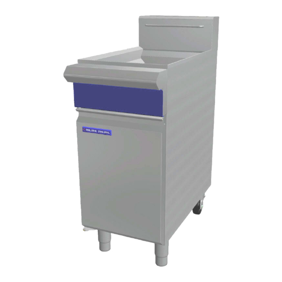
- Page 1 4 0 0 m m G a s F r y e r M o d e l G T 1 8 I N S T A L L A T I O N A N D O P E R A T I O N M A N U A L 236863-2...
- Page 2 (fax): 1800 350 281 NEW ZEALAND Moffat Limited Web: www.moffat.co.nz E.Mail: sales@moffat.co.nz Main Office: (tel): 0800 663328 UNITED KINGDOM Blue Seal Web: www.blue-seal.co.uk E.Mail: sales@blue-seal.co.uk Sales: (tel): +44 121 327 5575 (fax): +44 121 327 9711 Spares: (tel): +44 121 322 6640...
-
Page 3: Table Of Contents
Contents List BLUE SEAL GT18 - 400mm GAS FRYER (Single Tank - 18 Ltr) Part 1 Introduction..................2 Part 2 Specifications .................. 3 General ............................3 Gas Connection ......................... 3 Gas Supply Requirements ......................4 Part 3 Installation ..................4 Installation Requirements ...................... -
Page 4: Part 1 Introduction
Part 1 Introduction We are confident that you will be delighted with your Blue Seal 400mm Gas Fryer, and it will become a most valued appliance in your commercial kitchen. To ensure you receive the utmost benefit from your new Blue Seal Appliance, there are two important things you can do. -
Page 5: Part 2 Specifications
Part 2 Specifications Model Covered in this Specification - Gas Connection GT18 400mm GAS FRYER (Single Tank - 18 Ltr). Gas supply connection point is located 40mm from the right hand side, 24mm from the rear and 223mm from the floor. - Flexible Hose Connection If a Gas Hose assembly is used to connect this appliance, the hose and all fittings must have a... -
Page 6: Gas Supply Requirements
Part 2 Specifications Gas Supply Requirements - Non UK Models: Gas Natural LP Gas / Butane Town Gas (**) Input Rating 90 MJ/hr 90 MJ/hr 90 MJ/hr (N.H.G.C.) (85,300 Btu/hr) (85,300 Btu/hr) (85,300 Btu/hr) 1.13 - 2.0 kPa 2.75 - 3.0 kPa 0.75 - 1.5 kPa Supply Pressure (4.5”... -
Page 7: Part 3 Installation
LPG / Butane 24 m³/hr minimum. Town Gas 24 m³/hr minimum. Blue Seal gas fryers are designed to provide years of satisfactory service and correct installation is 3. Position the appliance in its approximate essential to achieve the best performance, working position. -
Page 8: Assembly
QUALIFIED SERVICE PERSON. 8. Measure Main Burner Operating Pressure at 1. BLUE SEAL Model Fryers do not require an Operating Pressure Test Point (Lower - Out) on electrical connection, they function totally on the Gas Control Valve. Adjust if required, as the gas supply only. -
Page 9: Commissioning
Part 3 Installation Commissioning The following commissioning checks must be carried out before the fryer is handed over for use, to ensure that the unit operates correctly and the operator(s) understand correct operating procedure. 1. Before leaving the new installation; WARNING: O NOT USE A NAKED FLAME TO CHECK FOR GAS LEAKAGES a. -
Page 10: Part 4 Operation
Components having adjustments protected (e.g. paint sealed) by the manufacturer should not be adjusted by the user / operator. Operation Guide Description of Controls 1. BLUE SEAL Fryers have been designed to provide A commercial gas fired Fryer using a single simplicity of operation and 100% safety Multi Jet Target ‘U’... -
Page 11: Before Use
Never allow shortening to smoke while melting as this indicates that the temperature is too high. NOTE: Blue Seal fryers can be used with both oil and If the shortening starts smoking, increase the shortening. -
Page 12: Lighting The Main Burner
5. Continue cooking until outside of food is brown maintain this temperature. and crisp and pieces are cooked through. 5. As a safety precaution this Blue Seal Fryer 6. Exact cooking time depends upon size of food features an Over-Temp Control which will ‘Turn pieces and whether food has been pre-cooked. -
Page 13: Part 5 Cleaning And Maintenance
Part 5 Cleaning and Maintenance General Draining and Cleaning Opening the Drain Valve WARNING: a. Lift the locking slide on valve handle (Fig 1) to release valve. DO NOT USE FLAMMIBLE SOLVENTS AND CLEANING AIDS ON b. While holding the locking slide in the OR IN CLOSE PROXIMITY TO THE FRYER WHILST THE FRYER IS STILL withdrawn position, rotate the handle HOT. -
Page 14: Weekly Cleaning
Part 5 Cleaning and Maintenance 4. Carefully open the drain valve to minimise 6. Empty the fryer and rinse thoroughly with water. splashing, and take care not to overfill the Use a 1 part vinegar to 15 parts water solution to container. -
Page 15: Part 6 Gas Conversion
Part 6 Gas Conversion Gas Conversion Procedure 5. Cut and remove any Disconnect Gas Cut Tie Connection cable ties as required Wraps 6. Disconnect the flexi AUTI ON tube gas connection at the top of the Gas Ensure that the Unit is isolated from the gas Control Valve. - Page 16 Part 6 Gas Conversion Main Burner Injectors Pilot Burner Flame Adjustment 1. To remove Main 1. Once main burner operating pressure has been Burner Injectors (Qty Injector set, adjust pilot burner supply so that the 9), use a ⅝” A/F impingement of the pilot flame on the spanner to prevent thermocouple and thermopile is correct and...
-
Page 17: Gas Specifications
Part 6 Gas Conversion Gas Specifications - Australia: Natural Gas LP Gas (Propane) Main Burner Injectors Ø 1.55mm Ø 0.95mm Pilot Burner Injectors 0.62 0.35 Pilot Screw Adjustment Full Out (CCW) 1½ turns out (CCW) 0.90 kPa (*) 2.50 kPa (*) Burner Operating Pressure (9.0 mbar) (25 mbar) -
Page 18: Part 7 Replacement Parts List
Part 7 Replacement Parts List Replacement Parts List IMPORTANT: Only genuine qualified replacement parts should be used for the servicing and repair of this appliance. The instructions supplied with the parts should be followed when replacing components. For further information and servicing instructions, contact your nearest qualified service branch (contact details are as shown on the reverse of the front cover of this manual).
Need help?
Do you have a question about the Evolution GT18 Series and is the answer not in the manual?
Questions and answers