Table of Contents
Advertisement
Quick Links
Advertisement
Table of Contents

Related Manuals for BlazeVideo A323


Summary of Contents for BlazeVideo A323
- Page 1 TRAIL CAMERA MODEL: A323 INSTRUCTION MANUAL V1.6...
-
Page 2: Table Of Contents
TABLE OF CONTENT 1. IN THE BOX..............1 2. IMPORTANT NOTE............1 3. INTRODUCTION............1 3.1. ABOUT THE CAMERA........1 3.2. APPLICATIONS...........3 4. PARTS AND CONTROLS..........3 5. INSTALLING THE BATTERIES AND SD CARD..6 5.1. LOADING BATTERIES........6 5.2. INSERTING THE SD CARD........7 6. USING THE CAMERA...........8 7. -
Page 3: In The Box
3. INTRODUCTION 3.1. ABOUT THE CAMERA The A323 trail camera is a new generation of digital scouting camera, it can be triggered by any movement of game in a location, detected by a highly sensitive Passive Infra-Red (PIR) - Page 4 still photos), or 1080P 30fps H.264 video clips with audio. The Camera features the all new innovative and ultra-clear Sony imaging technology. The camera encompasses all-new software innovations, smart illumination technology, blur reduction technology, auto noise reduction and dynamic exposure technology to deliver high resolution image quality, multi-zone detection, pre-activated technology and fast boot to deliver 0.1s fast trigger speed and 0.5s recovery time.
-
Page 5: Applications
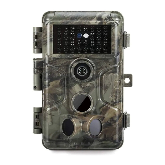
use and resistant against rain and snow. Operation Temperature -4~140°F. Support SD/SDHC/SDXC memory card, max capacity 512GB (user supplied). Extremely long in-field battery life up to 8 months in a stand-by state with 8 AA 1.5V batteries (user supplied). 3.2. - Page 6 Light Sensor Indicator IR LEDs Optical Microphone Lens Lock Hole Center PIR Motion Sensor Side PIR Side PIR Motion Sensor Motion Sensor Figure 1: Front View The camera provides the following connections for external devices: Mini USB port and SD card slot etc. (Figure 2). Tripod Base SD Card 1/4"...
- Page 7 Lock Strap Hole Buckle Figure 3: Back View The camera has a 2.4-inch built-in LCD screen, which can be used for reviewing pictures or videos and menu displaying, and unique keypad design for easy program and operation, 8 AA batteries slot supported (Figure 4). Color Screen Battery...
-
Page 8: Installing The Batteries And Sd Card
modes: OFF, ON, and SET (Figure 5). A control key interface with six keys is primarily used in SET mode to select operational functions and parameters. As shown in Figure.5, the keys can also perform a second function (shortcut operations in SET mode) in addition to their main function. -
Page 9: Inserting The Sd Card
Figure 6: Loading the Batteries 5.2. INSERTING THE SD CARD Insert the SD card (with the camera's power switch in the OFF position) before beginning to operate the camera. Don't insert or remove the SD card when the power switch is in the ON or 一... -
Page 10: Using The Camera
upwards. A "click" sound indicates that the card is installed successfully. If the wrong side of the card is facing up, you will not be able to insert it without force, there is only one correct way to insert cards. If the SD card is not installed correctly, the device will not display an SD card icon on the screen in SET mode. -
Page 11: Off Mode
ON mode: Power switch in the ON position. SET mode: Power switch in the SET position (screen is on). 7.1. OFF MODE The OFF mode is the "safe" mode when any actions must be taken, e.g., replacing the SD card or batteries, or transporting the device. - Page 12 in the menu by pressing MENU key, let you change the photo or video resolution, interval between photos, switch the time imprint on, etc. (See more in Section 8 ADVANCED SETTINGS). Moving the power switch to the SET position will turn on the screen display, and you will see an information screen that shows how many images have been taken, the battery level, camera or video mode, etc.
-
Page 13: Advanced Settings
8. ADVANCED SETTINGS The trail camera comes with preset manufacturer settings. You can change the settings to meet your requirements. Please make sure that the camera is in the SET mode. Once the camera screen is on, press MENU key to enter/exit the menu. Press the UP/DOWN key to move the marker, Press the LEFT/RIGHT key to change the setting, and press the OK key to confirm the change. - Page 14 more of the SD card capacity. Select video recording length. Note: Night videos are limited to a 10 seconds, maximum of 30 seconds to conserve the Video Optional batteries. If the video length is set to more Length from than 30 seconds, e.g. 60 seconds, the max 3s to 5m recording length at night will stay at 30 seconds.
- Page 15 as “Time Lapse”. Selecting On will activate the side motion sensors. It brings faster trigger speeds and helps capture fast moving animals. When any of the two side motion sensors detects a motion event, the camera will be Side Motion pre-activated.
- Page 16 date and time. Date input format may change. Please refer to “Date Format” parameter settings accordingly. D/M/Y Select date format which will be shown on Date Format M/D/Y the screen and each capture. Y/M/D Select time format which will be shown Time on the screen and each capture.
-
Page 17: Mounting And Positioning The Camera
code is lost, you can contact customer support to reset the password. All files will be deleted after formatting the SD card. We highly recommend you to format the SD card if it has been used Format SD Card previously in other devices. Caution: make sure wanted files on the SD card have been backed up first! Selecting Yes will return all your previous... -
Page 18: Sensing Angle And Distance Test
pulling the end of the strap firmly so there is no slack left (Figure 8). Note: it is not possible to use a cable lock (in the upper part of the bracket) and the strap at the same time. Using the tripod socket: The camera is equipped with a socket at the bottom end to enable mounting on a tripod or other mounting accessories with a standard UNC 1/4-20 thread screw (user supplied). -
Page 19: Switching On The Camera
indicates that position can be sensed. If it does not blink, that position is outside of the sensing area. (Note: The red light will blink only when the motion is within the sensing area of the central PIR sensor. The central sensor's sensing angle of view is 60°. -
Page 20: Review Photos Or Videos
(2) If you set the camera working mode as “Time Lapse” in the menu, once you switch to the ON mode, the camera will be ready to go into “Time Lapse” mode, then take images periodically according to your preset “Timelapse Interval” parameter, regardless of the settings “Detection Delay”. -
Page 21: Technical Specifications
11. TECHNICAL SPECIFICATIONS Element Description Working Mode Motion detection or Time Lapse Max. Pixel Size 24MP Lens F=1.6, FOV=63°, Auto IR-Cut IR Flash 100ft LCD Screen 2.4" Color screen Keypad 6 Keys, 1 Power switch SD, SDHC or SDXC standard-size memory card Memory (Not included), max capacity 512GB Picture... - Page 22 Password 4-Digit Code Camera Name 4-Character (A-Z, 0-9) Time Lapse 1 Sec. ~ 24 Hours Power Supply 8x1.5V AA Batteries (Not included) Stand-by Time 8 Months Auto Stand-by (Surveillance mode) in 5 minutes Auto Stand-by while no operation in SET mode 8V - Low Battery (Batteries die) Low Battery 9V - Night vision is unavailable in low voltage...
-
Page 23: Warranty
12. WARRANTY ONE YEAR LIMITED WARRANTY Your trail camera warranty covers your trail camera for one year after the original purchase date. We warrant that your camera will be free from defects in materials and workmanship when operated in normal use and conditions. This warranty does not cover consumer caused damages such as misuse, abuse, improper handling or installation, damaged caused by wild animals, or repairs attempted by someone other... -
Page 24: Fcc Compliance Statement
13. FCC COMPLIANCE STATEMENT This equipment has been tested and found to comply with the limits for a Class B digital device, pursuant to part 15 of the FCC Rules. These limits are designed to provide reasonable protection against harmful interference in a residential installation.
Need help?
Do you have a question about the A323 and is the answer not in the manual?
Questions and answers