Table of Contents
Advertisement
Advertisement
Table of Contents

Related Manuals for BlazeVideo A252


Summary of Contents for BlazeVideo A252
- Page 1 TRAIL CAMERA MODEL: A252 INSTRUCTION MANUAL V1.2...
-
Page 2: Table Of Contents
TABLE OF CONTENT 1. IN THE BOX..............1 2. IMPORTANT NOTE............1 3. INTRODUCTION............1 3.1. ABOUT THE CAMERA........1 3.2. APPLICATIONS...........3 4. PARTS AND CONTROLS..........3 5. INSTALLING THE BATTERIES AND SD CARD..6 5.1. LOADING BATTERIES........6 5.2. INSERTING THE SD CARD........7 6. USING THE CAMERA...........8 7. -
Page 3: In The Box
1. IN THE BOX 1 x Camera, 1 x Mounting Strap, 1 x Instruction Manual, 1 x Mini USB Cord Note: Memory card and batteries are not included (user supplied). 2. IMPORTANT NOTE Require eight (8) 1.5V AA Alkaline or Lithium batteries. We recommend the use of Energizer AA Lithium batteries in this camera to obtain maximum battery life. - Page 4 photos), 1296P 20fps or 1080P 30fps H.264 video clips. The Camera features the all new innovative imaging technology. The camera encompasses all-new software innovations, smart illumination technology, blur reduction technology, auto noise reduction and dynamic exposure technology to deliver high resolution image quality, and fast boot to deliver fast 0.3s trigger speed and 0.5s recovery time.
-
Page 5: Applications
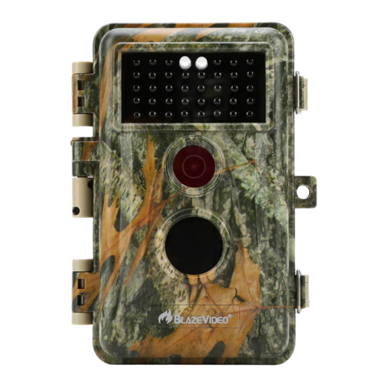
Support SD/SDHC/SDXC memory card, max capacity 512GB (user supplied). Extremely long in-field battery life up to 8 months in a stand-by state with 8 AA 1.5V batteries (user supplied). 3.2. APPLICATIONS The camera can be used as follows: For hunting and tracking animals’... - Page 6 Light Sensor Indicator IR LEDs Optical Lens Lock Hole PIR Motion Sensor Figure 1: Front View The camera provides the following connections for external devices: Mini USB port and SD card slot etc. (Figure 2). Tripod Base SD Card 1/4" - 20 Holder DC 12V/1A Plug 4.0x1.7mm...
- Page 7 Lock Strap Hole Buckle Figure 3: Back View The camera has a 2.4-inch built-in LCD screen, which can be used for reviewing pictures or videos and menu displaying, and unique keypad design for easy program and operation, 8 AA batteries slot supported (Figure 4). Color Screen Battery...
-
Page 8: Installing The Batteries And Sd Card
modes: OFF, ON, and SET (Figure 5). A control key interface with six keys is primarily used in SET mode to select operational functions and parameters. As shown in Figure.5, the keys can also perform a second function (shortcut operations in SET mode) in addition to their main function. -
Page 9: Inserting The Sd Card
Figure 6: Loading the Batteries 5.2. INSERTING THE SD CARD Insert the SD card (with the camera's power switch in the OFF position) before beginning to operate the camera. Don't insert or remove the SD card when the power switch is in the ON or 一... -
Page 10: Using The Camera
upwards. A "click" sound indicates that the card is installed successfully. If the wrong side of the card is facing up, you will not be able to insert it without force, there is only one correct way to insert cards. If the SD card is not installed correctly, the device will not display an SD card icon on the screen in SET mode. -
Page 11: Off Mode
ON mode: Power switch in the ON position. SET mode: Power switch in the SET position (screen is on). 7.1. OFF MODE The OFF mode is the "safe" mode when any actions must be taken, e.g., replacing the SD card or batteries, or transporting the device. - Page 12 in the menu by pressing MENU key, let you change the photo or video resolution, interval between photos, switch the time imprint on, etc. (See more in Section 8 ADVANCED SETTINGS). Moving the power switch to the SET position will turn on the screen display, and you will see an information screen that shows how many images have been taken, the battery level, camera or video mode, etc.
-
Page 13: Advanced Settings
8. ADVANCED SETTINGS The trail camera comes with preset manufacturer settings. You can change the settings to meet your requirements. Please make sure that the camera is in the SET mode. Once the camera screen is on, press MENU key to enter/exit the menu. Press the UP/DOWN key to move the marker, Press the LEFT/RIGHT key to change the setting, and press the OK key to confirm the change. - Page 14 720P videos, but creates larger files that take more of the SD card capacity. Select video recording length. Note: Night videos are limited to a 10 seconds, maximum of 30 seconds to conserve the Video Optional batteries. If the video length is set to more Length from than 30 seconds, e.g.
- Page 15 This feature helps you aim the camera at Motion Test your target area. Please refer to the details in Section 9.2. Setting time lapse interval. It takes effect ONLY when Mode is set as Time Lapse, the camera will automatically take photos/videos according to the set 1 hour, interval, regardless of whether the PIR...
- Page 16 Yellow Stone Park). This helps multi-camera users identify the location when reviewing the photos. Select On to show date, time, Info Strip temperature, moon phase on each capture. Selecting On option will cause the oldest files to be overwritten with new captures Loop when the SD card reaches its capacity.
-
Page 17: Mounting And Positioning The Camera
9. MOUNTING AND POSITIONING THE CAMERA 9.1. MOUNTING After you've set up the camera's parameters to your personal preferences at home, you're ready to take it outside and slide the power switch to "ON". When setting up the camera for scouting game or other outdoor applications, you must be sure to mount it in place correctly and securely. -
Page 18: Sensing Angle And Distance Test
Figure 8: Mounting the Camera 9.2. SENSING ANGLE AND DISTANCE TEST To test whether the camera can effectively monitor the area you choose, this test is recommended to check the sensing angle and monitoring distance of the camera. To perform the test: Switch the camera to the SET mode. -
Page 19: Switching On The Camera
The results of your testing will help you find the best placement when mounting and aiming the camera. The height away from the ground for placing the device should vary with the animal size appropriately. In general, 3 to 6 feet is preferred. You can avoid potential false triggers due to temperature and motion disturbances in front of the camera by not aiming it at a heat source or nearby tree branches or bush (especially on... -
Page 20: Review Photos Or Videos
10. REVIEW PHOTOS OR VIDEOS After you have setup, mounted and activated your CAMERA, you will of course be eager to return later and review the images it has captured for you. The camera stores photos and videos in the folder \DCIM\100MEDIA in the SD card. Photos are saved with file names like DSCF0001.JPG and videos like DSCF0001.MP4. - Page 21 Picture 24MP, 20MP, 16MP, 8MP, 4MP, 2MP Resolution 1296@20fps 16:9, Video Resolution 1080P@30fps 16:9, Aspect Ratio 720P@30fps 16:9 PIR Sensitivity High/Normal/Low PIR Sensing 75ft (Below 77°F/25°C) Distance PIR Sensing 70° Angle Trigger Time Approx. 0.3 second Trigger Interval 0sec.-60min, Programmable Shooting Numbers 3sec ~ 5min., Programmable...
- Page 22 Mini-USB, Standard-size SD card holder, Interface External Power (DC 12V/1A, Plug 4.0x1.7mm) Mounting Strap, Tripod Base (1/4-20) Waterproof IP66 Operation -4~140°F/-20~60°C Temperature Operation 5% ~ 95% Humidity Certificate FCC & CE & RoHS Product 6.1 x 4.4 x 3.0 inches Dimensions...
-
Page 23: Warranty
12. WARRANTY ONE YEAR LIMITED WARRANTY Your trail camera warranty covers your trail camera for one year after the original purchase date. We warrant that your camera will be free from defects in materials and workmanship when operated in normal use and conditions. This warranty does not cover consumer caused damages such as misuse, abuse, improper handling or installation, damaged caused by wild animals, or repairs attempted by someone other... -
Page 24: Fcc Compliance Statement
13. FCC COMPLIANCE STATEMENT This equipment has been tested and found to comply with the limits for a Class B digital device, pursuant to part 15 of the FCC Rules. These limits are designed to provide reasonable protection against harmful interference in a residential installation.
Need help?
Do you have a question about the A252 and is the answer not in the manual?
Questions and answers
It has a 12V/1A dc socket. Does this mean I can supply power from a convenient mains supply (with appropriate adaptor)?