Table of Contents
Advertisement
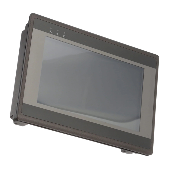
HMI5000P Series
Installation Guide
Introduction
Thank you for purchasing a Maple Systems HMI5000P Series graphic
industrial operator interface terminal. This booklet describes the steps
necessary for installing the following models:
HMI5070P
HMI5121P
HMI5150P
The HMI5000P Series touchscreens are configured using the
EasyBuilder Pro Software.
For information on programming and configuring the HMI, please refer to
the EasyBuilder Pro Programming Manual available for free download
on the Maple Systems website in the Support Center.
For additional information, please refer to the Support Center section of
the Maple Systems website, www.maplesystems.com.
The Support Center provides links to information such as Software
Downloads, Manuals, FAQs, Technical Notes, Training Videos, Sample
Projects, Controller Information Sheets, Controller Cables, and more.
Advertisement
Table of Contents

Related Manuals for Maple Systems HMI5000P Series


Summary of Contents for Maple Systems HMI5000P Series
- Page 1 HMI5000P Series Installation Guide Introduction Thank you for purchasing a Maple Systems HMI5000P Series graphic industrial operator interface terminal. This booklet describes the steps necessary for installing the following models: HMI5070P HMI5121P HMI5150P The HMI5000P Series touchscreens are configured using the EasyBuilder Pro Software.
-
Page 2: Warranty
HMI5000P Installation Guide Static Awareness Do NOT remove the rear cover of the HMI5000P Series product – doing so will void the warranty. When the rear cover is removed the circuitry inside is exposed to possible damage by electrostatic discharge during handling. -
Page 3: Technical Support
Web: www.maplesystems.com Installation of HMIs Information furnished by Maple Systems is believed to be accurate and reliable. However, no responsibility is assumed by Maple Systems for the use of this information, or for any infringements of patents or other rights of third parties which may result from its use. -
Page 4: Environmental Considerations
HMI5000P Installation Guide Environmental Considerations The HMI5000P Series is designed to operate in temperatures from 0° to 50°C (32° to 122°F). It is intended for indoor installations and may not be suitable for use in certain outdoor applications. Avoid installing the HMI in environments with severe mechanical vibration or shocks. -
Page 5: Cable Routing And Noise Immunity
HMI5000P Installation Guide Cable Routing and Noise Immunity Follow these guidelines when routing cables to the HMI: Always route the HMI communication cable and the power cable away from any AC voltage or rapidly switching DC control lines. Never bundle the HMI cables together with 120VAC power wires or with relay wiring. - Page 6 HMI5000P Installation Guide Figure 1: Typical Panel Layout 1010-1014 Rev 03 www.maplesystems.com...
-
Page 7: Control Panel Grounding
For a more in-depth overview of ground wiring techniques, refer to Technical Note #1027, “OIT Ground Wiring and Electrical Noise Reduction” in the Technical Notes section of the Maple Systems website. Installation It is necessary to follow all installation procedures described in this chapter for electrical noise immunity and CE compliance. - Page 8 HMI. The power cable for the HMI should be 18AWG, 2-conductor wire with a shield drain wire and protective shield (foil/braid). Cable (P/N 6030-0009) may be purchased by the foot from Maple Systems for constructing power cables. Always run the DC ground wire directly back to the signal return of the power supply.
-
Page 9: Panel Preparation
HMI5000P Installation Guide Panel Preparation To provide a NEMA 4 seal, a metal panel or mounting surface that does not flex more than 0.010” is required. Thin panels or surfaces may bow between the mounting clamps and not form a seal with the gasket. Allow sufficient clearance around the unit for the mounting hardware and cable connections. -
Page 10: Configuration Wiring
USB cable can complete a ground loop that may damage the HMI and PC. For this reason, Maple Systems highly recommends connecting your HMI to a PC via Ethernet. Maple Systems assumes no liability for ground-loop damage to HMI or PC. - Page 11 HMI5000P Installation Guide Ethernet If using a switch or router between the PC and the HMI, use a straight- through or crossover cable as required by the switch or router. In order to download a project to the HMI over Ethernet, the HMI must be assigned a unique IP address that is on the same subnet as the development PC.
-
Page 12: Maintenance
Improper use by setting to ON may damage the HMI. Contact Maple Systems for more information. Fusing Requirements If the display does not come on within two seconds of power up, remove power. -
Page 13: Serial Port Connections
HMI5000P Installation Guide USB/SD Ports The HMI5000P series HMIs each have an SD card slot and USB host port. These ports are designed for data storage only. Note: If connecting a USB hard drive, power the drive with its own power supply. - Page 14 HMI5000P Installation Guide 1010-1014 Rev 03 www.maplesystems.com...
- Page 15 HMI5000P Installation Guide 1010-1014 Rev 03 www.maplesystems.com...
- Page 16 Maple Systems Inc. 808 134 Street SW, Suite 120 Everett, WA 98204-7333 Phone: (425) 745-3229 Email: maple@maplesystems.com Web: www.maplesystems.com © 2020 Maple Systems Inc. All rights reserved.
Need help?
Do you have a question about the HMI5000P Series and is the answer not in the manual?
Questions and answers