Please read the operating instructions carefully before using this product, and save the operating
instructions for future use.
See page 91 for all model numbers.
Operating Instructions
MCO-170AIC
MCO-170AICUV
MCO-170AICUVH
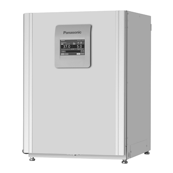
CO
Incubator
2
MCO-170AIC
MCO-170AICUV
MCO-170AICUVH
Series


Need help?
Do you have a question about the MCO-170AICUVH Series and is the answer not in the manual?
Questions and answers
What is the part number for the humidifying pan? What are the dimensions of it?