Table of Contents
Advertisement
Quick Links
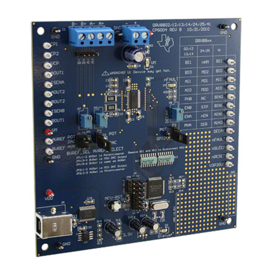
This document is provided as a supplement to the DRV8802, DRV8812, DRV8813, DRV8814, DRV8824,
DRV8825, DRV8841 and DRV8843 datasheets. It details the hardware implementation of the CPG004
DRV88xxEVM Customer Evaluation Module (EVM). On this document, DRV88xx will be used
interchangeably to refer to any of the aforementioned devices.
1
1.1
1.2
1.3
1.4
2
2.1
2.2
2.3
3
3.1
3.2
3.3
3.4
3.5
.................................................................................................................
4
1
2
3
4
DRV8802-12-13-14 Tab
5
6
7
8
9
10
11
12
13
14
1
SLVU361B - April 2010 - Revised October 2013
Submit Documentation Feedback
CPG004_DRV88xx Evaluation Modules
...............................................................................................................
.................................................................................................
.........................................................................................................
.............................................................................................................
......................................................................................................
...........................................................................................
...................................................................................
..................................................................................................
...........................................................................................................
....................................................................................
....................................................................................
....................................................................................
....................................................................................................
...........................................................................................................
...........................................................................................................
.......................................................................................................
..............................................................................................................
........................................................................................................
...................................................................................................
...............................................................................................
..............................................................................................................
................................................................................................................
................................................................................................
Copyright © 2010-2013, Texas Instruments Incorporated
SLVU361B - April 2010 - Revised October 2013
Contents
....................................................................
.................................................................................
.................................................................................
.......................................................................
List of Figures
List of Tables
............................................................
CPG004_DRV88xx Evaluation Modules
User's Guide
......................
...........................................
2
2
2
3
4
5
5
5
5
5
7
7
8
8
9
12
3
3
4
5
6
6
7
8
8
9
10
10
11
11
4
1
Advertisement
Table of Contents

Related Manuals for Texas Instruments CPG004DRV88 EVM Series


Summary of Contents for Texas Instruments CPG004DRV88 EVM Series
-
Page 1: Table Of Contents
........................ Step Control ....................Stepper Speed Calculator List of Tables ............BVREF Default Jumper Allocation on a Per Device Basis SLVU361B – April 2010 – Revised October 2013 CPG004_DRV88xx Evaluation Modules Submit Documentation Feedback Copyright © 2010–2013, Texas Instruments Incorporated... -
Page 2: Block Diagram
For those pins that change functionality depending on device flavor, a table is provided with corresponding function name on its particular column. CPG004_DRV88xx Evaluation Modules SLVU361B – April 2010 – Revised October 2013 Submit Documentation Feedback Copyright © 2010–2013, Texas Instruments Incorporated... -
Page 3: Jumpers
H Bridge, resulting in very poor motion or no motion at all. Figure 2. BVREF Select Jumper Configuration SLVU361B – April 2010 – Revised October 2013 CPG004_DRV88xx Evaluation Modules Submit Documentation Feedback Copyright © 2010–2013, Texas Instruments Incorporated... -
Page 4: Motor Outputs
(J3). Although feasible, we do not recommend the connection of any motor into the test clips as these are Kelvin connections and not rated for high current output. CPG004_DRV88xx Evaluation Modules SLVU361B – April 2010 – Revised October 2013 Submit Documentation Feedback Copyright © 2010–2013, Texas Instruments Incorporated... -
Page 5: Installing Drivers And Software
This function is achieved by using both MSP430 DAC outputs and is only available if respective jumpers are set for dual DAC connection (as default). SLVU361B – April 2010 – Revised October 2013 CPG004_DRV88xx Evaluation Modules Submit Documentation Feedback Copyright © 2010–2013, Texas Instruments Incorporated... -
Page 6: Drv8824-25 Gui
PWM slider in order to provide speed control per H Bridge on both directions per H Bridge. CPG004_DRV88xx Evaluation Modules SLVU361B – April 2010 – Revised October 2013 Submit Documentation Feedback Copyright © 2010–2013, Texas Instruments Incorporated... -
Page 7: The Menu
The DECAY pin is in reality a triple state input. The GPIO operates as HI and LO according to the checkbox. To have the DECAY pin floating, engaging mixed decay mode, simply remove the decay jumper JP3. SLVU361B – April 2010 – Revised October 2013 CPG004_DRV88xx Evaluation Modules Submit Documentation Feedback Copyright © 2010–2013, Texas Instruments Incorporated... -
Page 8: Updating Dac Output For Current Control (Vrefa And Vrefb)
0 to 255 are obtained. The MSP430 directly transforms this 8 bit number into the respective duty cycle. PWM frequency is around 31.25 kHz. Figure 9. Duty Cycle Indicator CPG004_DRV88xx Evaluation Modules SLVU361B – April 2010 – Revised October 2013 Submit Documentation Feedback Copyright © 2010–2013, Texas Instruments Incorporated... -
Page 9: Operating The Stepper Motor (Drv8824) 4 Schematics
Once the specified PPS speed has been achieved, the acceleration stops. When the motor stops, the inverse of the above description occurs. SLVU361B – April 2010 – Revised October 2013 CPG004_DRV88xx Evaluation Modules Submit Documentation Feedback Copyright © 2010–2013, Texas Instruments Incorporated... -
Page 10: Speed Control
The “Pulse Step” button allows for a single step to be issued. Remember that a STEP takes place when STEP goes from LO to HI. CPG004_DRV88xx Evaluation Modules SLVU361B – April 2010 – Revised October 2013 Submit Documentation Feedback Copyright © 2010–2013, Texas Instruments Incorporated... -
Page 11: Stepper Speed Calculator
While microstepping with 4 degrees of microstepping, a motor with 200 steps per revolution should be moving at 5 revolutions per second or 300 revolutions per minute. Figure 14. Stepper Speed Calculator SLVU361B – April 2010 – Revised October 2013 CPG004_DRV88xx Evaluation Modules Submit Documentation Feedback Copyright © 2010–2013, Texas Instruments Incorporated... - Page 12 Schematics www.ti.com Schematics See the following pages for schematics. CPG004_DRV88xx Evaluation Modules SLVU361B – April 2010 – Revised October 2013 Submit Documentation Feedback Copyright © 2010–2013, Texas Instruments Incorporated...
- Page 13 DRV8843EVM Quad Half H Bridge (2.5A) Size DWGNo. CPG004 On this document, D RV88xx refersto theDRV8802/12/13/14/24/25/41/43 devices Sheet 1 of 3 SLVU361B – April 2010 – Revised October 2013 CPG004_DRV88xx Evaluation Modules Submit Documentation Feedback Copyright © 2010–2013, Texas Instruments Incorporated...
- Page 14 DRV8841EVM Quad Half H Bridge (2.5A) Populatefor DRV8802/12/13/14 DRV8843EVM Quad Half H Bridge (2.5A) Populatefor DRV8824/25 Size DWGNo. Populatefor DRV8841/43 CPG004 Sheet 2 of 3 CPG004_DRV88xx Evaluation Modules SLVU361B – April 2010 – Revised October 2013 Submit Documentation Feedback Copyright © 2010–2013, Texas Instruments Incorporated...
- Page 15 DRV8825EVM Bipolar StepperDriver with Indexer (2.5A) DRV8841EVM Quad Half H Bridge (2.5A) DRV8843EVM Quad Half H Bridge (2.5A) CPG004 Sheet 3 of 3 SLVU361B – April 2010 – Revised October 2013 CPG004_DRV88xx Evaluation Modules Submit Documentation Feedback Copyright © 2010–2013, Texas Instruments Incorporated...
- Page 16 Changed figure 5 and supporting text below image NOTE: Page numbers for previous revisions may differ from page numbers in the current version. Revision History SLVU361B – April 2010 – Revised October 2013 Submit Documentation Feedback Copyright © 2010–2013, Texas Instruments Incorporated...
- Page 17 Any exceptions to this are strictly prohibited and unauthorized by Texas Instruments unless user has obtained appropriate experimental/development licenses from local regulatory authorities, which is responsibility of user including its acceptable authorization.
- Page 18 FCC Interference Statement for Class B EVM devices This equipment has been tested and found to comply with the limits for a Class B digital device, pursuant to part 15 of the FCC Rules. These limits are designed to provide reasonable protection against harmful interference in a residential installation. This equipment generates, uses and can radiate radio frequency energy and, if not installed and used in accordance with the instructions, may cause harmful interference to radio communications.
- Page 19 Also, please do not transfer this product, unless you give the same notice above to the transferee. Please note that if you could not follow the instructions above, you will be subject to penalties of Radio Law of Japan. Texas Instruments Japan Limited (address) 24-1, Nishi-Shinjuku 6 chome, Shinjuku-ku, Tokyo, Japan http://www.tij.co.jp...
- Page 20 FDA Class III or similar classification, then you must specifically notify TI of such intent and enter into a separate Assurance and Indemnity Agreement. Mailing Address: Texas Instruments, Post Office Box 655303, Dallas, Texas 75265 Copyright © 2013, Texas Instruments Incorporated...
- Page 21 IMPORTANT NOTICE Texas Instruments Incorporated and its subsidiaries (TI) reserve the right to make corrections, enhancements, improvements and other changes to its semiconductor products and services per JESD46, latest issue, and to discontinue any product or service per JESD48, latest issue.
Need help?
Do you have a question about the CPG004DRV88 EVM Series and is the answer not in the manual?
Questions and answers