Sign In
Upload
Download
Table of Contents
Contents
Add to my manuals
Delete from my manuals
Share
URL of this page:
HTML Link:
Bookmark this page
Add
Manual will be automatically added to "My Manuals"
Print this page
×
Bookmark added
×
Added to my manuals
Manuals
Brands
JLG Manuals
Scissor Lifts
R2632
Operation and safety manual
JLG R2632 Operation And Safety Manual
Hide thumbs
1
2
3
4
5
6
Table Of Contents
7
8
9
10
11
12
13
14
15
16
17
18
19
20
21
22
23
24
25
26
27
28
29
30
31
32
33
34
35
36
37
38
39
40
41
42
43
44
45
46
47
48
49
50
51
52
53
54
55
56
57
58
59
60
61
62
63
64
65
66
67
68
69
70
71
72
73
74
75
76
77
78
79
80
81
82
83
84
85
86
87
88
89
90
91
92
93
94
95
page
of
95
Go
/
95
Contents
Table of Contents
Bookmarks
Table of Contents
Table of Contents
Section 1 - Safety Precautions
General
Pre-Operation
Operator Training and Knowledge
Workplace Inspection
Machine Inspection
Operation
General
Trip and Fall Hazards
Electrocution Hazards
Tipping Hazards
Crushing and Collision Hazards
Towing, Lifting, and Hauling
Maintenance
Maintenance Hazards
Battery Hazards
Section 2 - User Responsibilities, Machine Preparation, and Inspection
Personnel Training
Operator Training
Training Supervision
Operator
Machine Familiarization
Preparation, Inspection, and Maintenance
Inspection and Maintenance Table
Pre-Start Inspection
Walk-Around Inspection
Inspection Diagram
Function Check
Section 3 - Machine Controls, Indicators, and Operation
General
Description
Operating Characteristics and Limitations
Placards
Capacities
Stability
Platform Loading
Battery Charging
Machine Control Locations
Ground Control Console
Ground/Platform/Off Key Selector Switch
Platform Lift/Lower Switch
Inverter ON/OFF Switch (if Equipped)
Ground Emergency Stop Switch
Hourmeter
Overload Indicator (LSS)
MDI Indicator (if Equipped)
Platform Control Station
Emergency Stop Switch
Lift/Drive Selector Switch
Forward/Reverse/Lift/Lower Directional Arrow
Drive/Lift/Steer Joystick Control
Steering and Traveling
Steering
Traveling Forward and Reverse
Raising and Lowering Platform
Arm Guards (if Equipped)
Overload Indicator (LSS)
Tilt Indicator Warning Light and Alarm
Variable Tilt - Platform Restricted Height Indicator
Horn
Alarm
Battery Charge Indicator
System Fault Indicator
Indoor/Outdoor Operation Indicator
Indoor/Outdoor Operation Mode Switch
Low/High Drive Speed
Grade and Sideslope
3.10 Platform Extension
Platform Rails Fold-Down Procedure
Platform with Rail-In-Rail Extension Deck
Platform with Dual Rails Extension Deck
3.12 Platform Manual Descent
3.13 Parking and Stowing Machine
3.14 Machine Lifting and Tie down
Towing
Hydraulic Brake Release
Push Button Brake Release (aus Market Only)
Section 4 - Emergency Procedures
General Information
Incident Notification
Emergency Operation
Operator Unable to Control Machine
Righting of Tipped Machine
Platform Caught Overhead
Platform Manual Descent
Section 5 - Accessories
Available Accessories
Options/Accessories Relationship Table
DC/Ac Power Inverter
Specifications
Safety Precautions
Preparation and Inspection
Operation
Pipe Racks
Safety Precautions
Preparation and Inspection
Operation
Anti-Vandalism Package
Rail-Mounted Platform Extension Handles
Operation
Footswitch
Operation
Magnetic Gate Latch
Jlg™ Mobile Control
Download
Operation
Document Resources
Section 6 - Specifications and Operator Maintenance
General Information
Other Publications Available Specific to this Machine
Serial Number Identification
Supplemental Information
Machine Specifications
Operating Specifications
Machine Dimensions
Maximum Allowable Operating Slope
Platform Capacities
Tires
Batteries
Battery Charger
Specifications
Delta-Q
Eagle Performance
Green Power (China (GB) Only)
Lubrication
Capacities
Specifications
Hydraulic Oil Operating Temperature Chart
Operator Maintenance
Engaging the Safety Prop
Hydraulic Oil Check Procedure
Battery Maintenance and Safety Practices
Battery Quick-Disconnect
Tire Wear and Damage
Wheel and Tire Replacement
Wheel Installation
Decal Installation
Diagram
Decals
Diagnostic Trouble Codes (Dtc)
Advertisement
Quick Links
1
Diagram
2
Diagnostic Trouble Codes (Dtc)
Download this manual
Operation and Safety Manual
Original Instructions - Keep this manual with the machine at all times.
Models
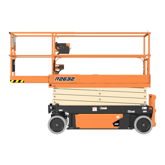
R2632
R3246
PVC 1910
31215090
ANSI
AS/NZS
GB
®
October 4, 2019 - Rev B
Table of
Contents
Previous
Page
Next
Page
1
2
3
4
5
Advertisement
Table of Contents
Need help?
Do you have a question about the R2632 and is the answer not in the manual?
Ask a question
Questions and answers
Related Manuals for JLG R2632
Scissor Lifts JLG R1532i Operation And Safety Manual
(102 pages)
Scissor Lifts JLG R4045 Operation And Safety Manual
(126 pages)
Scissor Lifts JLG R3246 Operation And Safety Manual
(95 pages)
Scissor Lifts JLG R2646 Operation & Safety Manual
(128 pages)
Scissor Lifts JLG AE1932 Operation And Safety Manual
(156 pages)
Scissor Lifts JLG 1532R Operation And Safety Manual
(98 pages)
Scissor Lifts JLG 12SP Service And Maintenance Manual
(62 pages)
Scissor Lifts JLG 3369LE Service And Maintenance Manual
(158 pages)
Scissor Lifts JLG 4045R Service Maintenance Manual
(180 pages)
Scissor Lifts JLG 2032E2 Operator's And Safety Manual
Electric scissor lifts (48 pages)
Scissor Lifts JLG 260MRT Service And Maintenance Manual
(107 pages)
Scissor Lifts JLG ES3246 Operating Instructions
(3 pages)
Scissor Lifts JLG AM Series Service And Maintenance Manual
(84 pages)
Scissor Lifts JLG 260MRT Operating Instructions
(3 pages)
Scissor Lifts JLG Commander CM1432 Operators & Safety Service & Maintenance Illustrated Parts Manual
(86 pages)
Scissor Lifts JLG 2632R Service Maintenance Manual
(195 pages)
This manual is also suitable for:
R3246
Table of Contents
Print
Rename the bookmark
Delete bookmark?
Delete from my manuals?
Login
Sign In
OR
Sign in with Facebook
Sign in with Google
Upload manual
Upload from disk
Upload from URL


Need help?
Do you have a question about the R2632 and is the answer not in the manual?
Questions and answers