Table of Contents
Advertisement
Quick Links
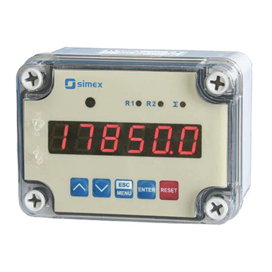
Firmware: v.6.00 or higher
•
Input type: 0/4-20 mA, 0/1-5V, 0/2-10V
•
Wall mounting case IP 67
•
Read the user's manual carefully before starting to use the unit or software.
Producer reserves the right to implement changes without prior notice.
2014.11.06
User manual
METER
SRP-N1186
Assisting the automation
industry since 1986
SRP-N1186_INSSXEN_v.1.00.001
Advertisement
Table of Contents

Related Manuals for Simex SRP-N1186


Summary of Contents for Simex SRP-N1186
- Page 1 Assisting the automation industry since 1986 User manual METER SRP-N1186 Firmware: v.6.00 or higher • Input type: 0/4-20 mA, 0/1-5V, 0/2-10V • Wall mounting case IP 67 • Read the user's manual carefully before starting to use the unit or software.
-
Page 2: Table Of Contents
User manual - METER SRP-N1186 CONTENTS 1. BASIC REQUIREMENTS AND USER SAFETY..................3 2. GENERAL CHARACTERISTICS........................4 3. TECHNICAL DATA............................5 4. DEVICE INSTALLATION..........................7 4.1. UNPACKING............................7 4.2. ASSEMBLY............................7 4.3. CONNECTION METHOD........................8 4.4. MAINTENANCE..........................19 5. FRONT PANEL DESCRIPTION........................20 6. PRINCIPLE OF OPERATION........................20 6.1. MEASUREMENT MODE........................20... -
Page 3: Basic Requirements And User Safety
User manual - METER SRP-N1186 Explanation of symbols used in the manual: - This symbol denotes especially important guidelines concerning the installation and operation of the device. Not complying with the guidelines denoted by this symbol may cause an accident, damage or equipment destruction. -
Page 4: General Characteristics
The selection of active input is realised by software, and selected input can be changed at any time. Additionally the SRP-N1186 allows user to select a conversion characteristic of several kinds: linear, square, square root, user defined (max.20 points length) and volume characteristics of a cylindrical tank in the vertical and horizontal position. -
Page 5: Technical Data
User manual - METER SRP-N1186 3. TECHNICAL DATA Power supply voltage 85...230...260V AC/DC; 50 ÷ 60 Hz (separated) (depending on version) or 19... 24 ...50V DC and 16... 24 ...35V AC (separated) External fuse (required) T - type, max. 2 A Power consumption max. - Page 6 User manual - METER SRP-N1186 range max. 0 ÷ 11V Active voltage output (optional, for two relays or two OC-type output version only) Load resistance min. 2000 Ω Temperature stability 50 ppm / °C Display range -99999 ÷ 999999, plus decimal point...
-
Page 7: Device Installation
User manual - METER SRP-N1186 This is a class A unit. In a residential or a similar area it can cause radio frequency interference. In such cases the user can be requested to use appropriate preventive measures. 4. DEVICE INSTALLATION The unit has been designed and manufactured in a way assuring a high level of user safety and resistance to interference occurring in a typical industrial environment. -
Page 8: Connection Method
User manual - METER SRP-N1186 110 mm 67 mm 90 mm Figure 4.1. Device and assembly dimensions 4.3. CONNECTION METHOD Caution - Installation should be conducted by qualified personnel . During installation all available safety requirements should be considered. The fitter is responsible for executing the installation according to this manual, local safety and EMC regulations. - Page 9 User manual - METER SRP-N1186 - If the unit is equipped with housing, covers and sealing to, protecting against water intrusion, pay special attention to their correct tightening or clamping. In the case of any doubt consider using additional preventive measures (covers, roofing, seals, etc.).
- Page 10 User manual - METER SRP-N1186 Figure 4.3. Method of connecting cables to the clamping connectors All connections must be made while power supply is disconnected ! 0/1 - 5V 0/2 - 10V (option) (option) RS - 485 12 11 10 9 8 7...
- Page 11 User manual - METER SRP-N1186 OC1, OC2: U max = 30V DC, max = 30mA, max = 100mW 0/1 - 5V 0/2 - 10V RS - 485 (option) (option) 12 11 10 9 8 7 (+5%, -10%) Imax = 100 mA 0/4 - 20mA Figure 4.5.
- Page 12 User manual - METER SRP-N1186 OC1: U max = 30V DC, max = 30mA, max = 100mW 0/1 - 5V 0/2 - 10V ACTIVE current output RS - 485 (option) (option) 12 11 10 9 8 7 (+5%, -10%) Imax = 100 mA 0/4 - 20mA Figure 4.7.
- Page 13 User manual - METER SRP-N1186 OC1: U max = 30V DC, max = 30mA, max = 100mW 0/1 - 5V Passive, isolated 0/2 - 10V current output 4÷20mA RS - 485 (option) (option) 12 11 10 9 8 7 (+5%, -10%)
- Page 14 User manual - METER SRP-N1186 OC1: U max = 30V DC, max = 30mA, max = 100mW 0/1 - 5V 0/2 - 10V ACTIVE voltage output RS - 485 (option) (option) 12 11 10 9 8 7 (+5%, -10%) Imax = 100 mA 0/4 - 20mA Figure 4.11.
- Page 15 User manual - METER SRP-N1186 internally connected 24V DC 13 12 11 10 9 8 7 13 12 11 10 9 8 7 Figure 4.14. Connection of voltage converters 5 4 3 FUSE FUSE Depending on version: 85...230...260V AC/DC; 50 ÷ 60 Hz or 19...24...50V DC and 16...24...35V AC...
- Page 16 User manual - METER SRP-N1186 Figure 4.16. Examples of suppression circuit connection: a) to relay terminals; b) to the inductive load Logic controller LED 10 mA voltage input Figure 4.17. Example of OC-type outputs connection ACTIVE current output Logic controller...
- Page 17 User manual - METER SRP-N1186 PASSIVE Current output Logic controller Isolation loss Current input 4-20mA Figure 4.19. Example of passive current outputs connection (for device with passive current output only) ACTIVE voltage output Logic controller voltage input 0 - 10V Figure 4.20.
- Page 18 Current source 0 - 20mA or 4 - 20mA galvanic isolation Figure 4.22. Serial connection of active 2-wire sensor with SRP-N1186 unit and other current measurement device (e.g. PLC controller). Connected internally 12 11 10 9 8 7 galvanic isolation Figure 4.23.
-
Page 19: Maintenance
User manual - METER SRP-N1186 Calculation of maximal allowable resistance of separator's input Maximal resistance of the input (R ) and wires (R ) are calculated for circuit from G max. W max. Figure 4.23 . Used symbols are described below. -
Page 20: Front Panel Description
User manual - METER SRP-N1186 5. FRONT PANEL DESCRIPTION alarm LED indicator (AL) Thresholds exceeding LED indicators (R) infrared receiver display ENTER RESET programming pushbuttons MENU Symbols and functions of push-buttons: Symbol used in the manual: [ESC/MENU] Functions: MENU •... - Page 21 User manual - METER SRP-N1186 ”Lo r” parameter ”Hi r” parameter nominal measurement range 4 mA 20 mA permissible measurement range Figure 6.1. Definitions of measurement ranges in mode 4 ÷ 20mA If the result of measurement exceeds the permissible measurement range, warning ”-Hi-” or ”-Lo-”...
-
Page 22: Detection Of The Peak Values
User manual - METER SRP-N1186 6.2. DETECTION OF THE PEAK VALUES The SRP-N1186 controller is equipped with peaks detection function. It can detect a peaks of the input signal and display their values. Presets connected with this function are placed in ”HOLd” menu (see description of ”HOLd” menu). The detection of the peak can be done if the measured signal raises and drops of value at least equal to parameter ”PEA”... -
Page 23: Control Of The Relay Outputs
User manual - METER SRP-N1186 6.3. CONTROL OF THE RELAY OUTPUTS The control of the object (measured signal) is realized via relay outputs. Front panel LEDs named “ R ” indicates the state of particular relay output. If device is not equipped with one or more relay outputs, menus refer to this relays are available, but apply to LED indicators only. -
Page 24: One Threshold Mode
User manual - METER SRP-N1186 6.3.1. One threshold mode Figure 6.6 presents the principle of relay outputs operation for one threshold mode, and an example values of other parameters. measured “SEtP” parameter displayed value signal (expected signal value) zone A “HYSt”... -
Page 25: Two Thresholds Mode
User manual - METER SRP-N1186 The state of relay output while the input value exceeds the border values (points A, B, C, D) is described by parameter “modE”. The relay can be turned on ( “modE” = ”on” ), or turned off (“modE”... -
Page 26: Device Programming
User manual - METER SRP-N1186 Figure 6.7 presents the principle of relay outputs operation for two thresholds mode, and an example values of other parameters. In this mode parameter “SEt2” is accessible in common with “SEtP” , this parameter describes a second threshold of the relay output. The parameters “HYSt”, “modE”, “t on”, “toFF”, “unit”... -
Page 27: Parameters Edition
User manual - METER SRP-N1186 Functions of the buttons while sub-menu and parameters choice: Selection of sub-menu or parameter for editing. Name of selected item (sub- menu or parameter) is displayed. Operation of [ENTER] button depend on present menu position: ENTER •... -
Page 28: Switch Parameters ("List" Type)
User manual - METER SRP-N1186 Press [ENTER] at least 2 seconds to accept the changes, after that question “Set?” is displayed, and user must to confirm (or cancel) the changes. To conform changes (and story it in EEPROM) press [ENTER] button shortly after “SEt?” is displayed. To cancel the changes press [ESC] button shortly after “SEt?”... -
Page 29: Rel1" Menu
User manual - METER SRP-N1186 7.3.1. “rEL1” menu This menu allows to configure the operation mode of relays and LEDs marked „ R ” (e.g. „ R1 ”). If there are few relay outputs available, then every output has its own configuration menu (e.g. - Page 30 User manual - METER SRP-N1186 - two threshold mode, relay is turned ON when the input value is bigger “out” than “bigger threshold + HYSt” and lower than “lower threshold – HYSt” , and turned on when the input signal is contained in the second zone.
-
Page 31: Inpt" Menu
User manual - METER SRP-N1186 If option “noCH” is selected for “AL” parameter, behaviour of the relay may • depend on “FiLt” parameter in some cases. If “FiLt” is set to big value and the input signal drops, result value of the measure will change slow, causes of turning on or off relay due to thresholds values. - Page 32 User manual - METER SRP-N1186 These parameters describe the values displayed for minimum and maximum input “Lo C” signal value for selected input type. For example, if input type is set to 4-20 mA “Lo “Hi C” C” parameter defines the value displayed when input current is equal 4 mA, and “Hi C”...
- Page 33 User manual - METER SRP-N1186 The unit value of “ t Sn ” parameter is 100-fold less than the unit value of • other parameters defining cylindrical tank, i.e. if we set value 10.00 in “ t Sh ” parameter and set value 08.00 in " t Sn " parameter this mean that value of “t Sn”...
- Page 34 User manual - METER SRP-N1186 t h3 t Sh t h2 h~I[mA] t Sn t h1 Figure 7.1 Parameters of cylindrical tank in vertical position. t h1 t h2 t h3 t Sh h~I[mA] t Sn Figure 7.2 Parameters of cylindrical tank in horizontal position.
- Page 35 User manual - METER SRP-N1186 (parameter “CHAr” = ”USEr” ) the If user defined characteristic is selected parameters „Lo C” and „Hi C” are not available for modification, due to their values are calculated from defined characteristic. “AddP” - this menu allow user to add single point to the user defined characteristic.
-
Page 36: Outp" Menu
User manual - METER SRP-N1186 ”Lo r” = 75,0% (3 mA) ”Hi r” = 5,0 % (1 mA) nominal measurement range (4-20mA) [mA] permissible measurement range measurement result is displayed display display regardless on nominal range exceeding message ”-Lo-” message ”-Hi-”... - Page 37 User manual - METER SRP-N1186 “4-20” - current output enabled with 4 ÷ 20 mA mode, ”modb” - current output controlled via RS-485 interface. For passive current output: ”oFF” - current output disabled, “4-20” - current output enabled with 4 ÷ 20 mA mode, ”modb”...
-
Page 38: Bri" Parameter
User manual - METER SRP-N1186 This parameter can be set from 0 to 19.999% (for active and passive current output) or from 0 to 9.999% (for active voltage output). In example on page 51 of the DISPLAY VALUES CALCULATION paragraph the procedure of the analogue outputs determining is presented in details. -
Page 39: Secu" Menu
User manual - METER SRP-N1186 “HdiS” - type of displayed values: ”rEAL” - current value is displayed, ”HOLd” - peak (drop) value is displayed, “H r1”, “H r2” - relay/LED outputs ( R1, R2) operation mode: ”rEAL” - relay/LED operates depend on the current value, ”HOLd”... -
Page 40: Edit" Parameter
User manual - METER SRP-N1186 The access to registers no 05h and 06h cant be denied by ”mbAc” parameter (see: LIST OF REGISTERS). ”mbtO” - this parameter defines maximal time (sec) between following frames received by the device. If the delay will be greater than the value of ”mbtO” parameter, the relays and analogue outputs which are controlled via RS-485 interface, will set to alert state (see "OUtP"... -
Page 41: Menu Structure
User manual - METER SRP-N1186 7.4. MENU STRUCTURE Measurement mode Press and hold at least 2 seconds MENU MENU 0 _ _ _ 4-digit user password entering (if it is different from „0000”) ENTER ENTER ENTER MENU rEL1 Parameter SEtP... - Page 42 User manual - METER SRP-N1186 See previous page ENTER ENTER Parameter MENU modE HOLd edition ENTER MENU timE Hdis MENU H r1 H r2 HOut option ENTER ENTER MENU Parameter SECU Scod edition ENTER MENU A r1 MENU A r2...
-
Page 43: The Alarm Led
User manual - METER SRP-N1186 8. THE ALARM LED The ALARM LED (AL) is turned on when input signal is out of the permissible input range. See parameters: “tyPE” , “Lo r” and “Hi r” in paragraph „InPt” menu. 9. OVER-CURRENT PROTECTION The current input of the device is equipped with over-current protection circuit. -
Page 44: Linear Characteristic
User manual - METER SRP-N1186 10.1.1. Linear characteristic The normalized result is converted by fixed coefficients determined by “Lo C” and “Hi C” parameters (when the normalized results is equal 0, then value “Lo C” is displayed, and when the normalized results is equal 1, then value “Hi C” is displayed). Expression presented below... -
Page 45: Square Root Characteristic
User manual - METER SRP-N1186 10.1.3. Square root characteristic The normalized result is rooted and further conversion is done as for linear characteristic. Conversion is made accordingly with the expression: × "Hi C" −"Lo C" "Lo C" , where W means the displayed value. -
Page 46: Volume Characteristics Of A Cylindrical Tank
User manual - METER SRP-N1186 Normalized measurement I (for 0-20 mA range) 0,35 5-elements characteristic X (PH) = „70.0.” Y (PH) X = „35.0.” Y (PL) X (PL) = „50.0.” X = „20.0.” Prąd wejściowy [mA] X = „90.0.” X = „100.0.”... -
Page 47: Examples Of Calculations
User manual - METER SRP-N1186 Volume of tank can be write by general formula: ∫ ⋅dh Possible combination of tank shape for calculation the volume: cylindrical tank in vertical position cylindrical tank in horizontal position parameter t h2=0 t h3=0... - Page 48 User manual - METER SRP-N1186 Example 3: The linear characteristic Let the input mode = 4-20 mA, and parameters “Lo C” and “Hi C” equal to -300 and 1200 respectively. The calculations will be done for three different input currents from example 2.
- Page 49 User manual - METER SRP-N1186 Example 6: The user defined characteristic Let the input mode = 4-20 mA, and the user selected the 10 segment characteristic. To do this it is necessary to enter X and Y coordinates of 11 points (see Menu ”inPt”).
- Page 50 User manual - METER SRP-N1186 „ t Sn ”=00,00 „t Sh”=10,00 „t h1”=00,00 „ t h2 ”=10,00 „t h3”=00,00 „ t d ”=04,00 Input current [mA] Figure 10.6 The volume characteristic of tank depending on input current in 4÷20mA range.
- Page 51 User manual - METER SRP-N1186 I [mA] Figure 10.7 The volume characteristic of tank depending on input current in 4÷20mA range. Example 9 : Analogue output value calculation Lets assume that we have active current output and its parameters are: “modE”...
-
Page 52: The Modbus Protocol Handling
User manual - METER SRP-N1186 11. THE MODBUS PRO TOCOL HANDLING Transmission parameters: 1 start bit, 8 data bits, 1 or 2 stop bit (2 bits are send, 1 and 2 bits are accepted when receive), no parity control Baud rate:... - Page 53 User manual - METER SRP-N1186 Register Write Range Register description “CHAr” parameter in “InPt” menu (characteristic type) 0 - linear ; 1 - square; 2 - square root; 3 - user defined; 4 - volume 0 ÷ 5 characteristics of a cylindrical tank in the vertical position; 5 - volume characteristics of a cylindrical tank in the horizontal position 0 ÷...
- Page 54 User manual - METER SRP-N1186 Register Write Range Register description “t h2” parameter in “InPt” menu, no decimal point included – lower see descr. word “t h3” parameter in “InPt” menu, no decimal point included – higher see descr. word “t h3”...
- Page 55 User manual - METER SRP-N1186 Register Write Range Register description “SEt2” parameter in “rEL1” menu, no decimal point included – see descr. lower word “SEtP” parameter in “rEL2” menu, no decimal point included – see descr. higher word “SEtP” parameter in “rEL2” menu, no decimal point included – lower see descr.
- Page 56 User manual - METER SRP-N1186 Register Write Range Register description The value of „X” coordinate of point no. 1 of the user defined see descr. characteristic, expressed in 0.1% – lower word The value of „Y” coordinate of point no. 1 of the user defined see descr.
- Page 57 User manual - METER SRP-N1186 Register Write Range Register description “Lo r” parameter in “OUtP” menu for passive current output, see descr. expressed in 0.001% – lower word “Hi r” parameter in “OUtP” menu for active and passive current see descr.
-
Page 58: Transmission Errors Description
Data byte count in answer frame DATA H,L Data byte (Hi and Lo byte) CRC L,H CRC error check (Hi and Lo byte) 1. Read of the displayed value (measurement), SRP-N1186 device address = 01h: ADDR FUNC REG H,L COUNT H,L... - Page 59 User manual - METER SRP-N1186 b) The answer (if an error occur): ADDR FUNC ERROR CRC L,H ERROR - error code = 60h, bottom border of the measurement range is exceeded 2. Read of device ID code ADDR FUNC REG H,L...
-
Page 60: Default And User's Settings List
User manual - METER SRP-N1186 5. Read of the registers 1, 2 and 3 in one message (example of reading a number of registries in one frame): ADDR FUNC REG H,L COUNT H,L CRC L,H COUNT L - the count of being read registers (max.16) - Page 61 User manual - METER SRP-N1186 Desc. Parameter Description Default value User's value page toFF Turn off delay of relay R2 unit Unit of “t on”, “toFF” parameters of relay R2 Reaction for critical situation of relay R2 Configuration of measurement input (“inPt” menu)
- Page 62 User manual - METER SRP-N1186 Desc. Parameter Description Default value User's value page Active voltage output configuration (“OUtP” menu) Omod Active voltage output mode „0-10” (V) OUtL Display value for 0 V, 1 V or 2 V voltage output 0.000...
- Page 63 User manual - METER SRP-N1186...
- Page 64 SIMEX Sp. z o.o. ul. Wielopole 11 80-556 Gdańsk Poland tel.: (+48 58) 762-07-77 fax: (+48 58) 762-07-70 http://www.simex.pl e-mail: info@simex.pl...
Need help?
Do you have a question about the SRP-N1186 and is the answer not in the manual?
Questions and answers