Table of Contents
Advertisement
Quick Links
Advertisement
Table of Contents

Subscribe to Our Youtube Channel
Related Manuals for FlowLine DataLoop LI24 Series


Summary of Contents for FlowLine DataLoop LI24 Series
- Page 1 Quick S Start ©20 19 Flowline, Inc. All R Rights Reser rved e in USA Flowlin ne, Inc. | 10500 Hu umbolt Street, Los Alamitos, CA 9072 20 p 562.598.3015 5 f 562.431.8507 w flowline.com LIN66 6 06QS_FL_A 02/1 QS302110A...
-
Page 2: Ordering Information
The LI24 Quick Start is meant to show some of the more common setup solutions to getting the LI24 up and running quickly. If you run into an issue that is not addressed here or wish to install or set up with a non-standard configuration, please address the LI24 Manual or refer to the Flowline website at flowline.com. -
Page 3: Hazardous Area Approvals
GENERAL COMPLIANCE INFORMATION ELECTROMAGNETIC COMPATIBILITY EMC Emissions CFR 47 FCC Part 15 Subpart B Class A emissions requirements (USA) AS/NZS CISPR 11:2004 Class A ISM emissions requirements (Australia) EN 55011:2009/A1:2010 Group 1 Class A ISM emissions requirements (EU) ... - Page 4 ATEX/IECEx SPECIAL CONDITIONS FOR SAFE USE The following conditions relate to safe installation and/or use of the equipment. • The permitted ambient temperature range for the LI24 is -40°C to 70°C. • The equipment must be installed in an enclosure which provides a minimum degree of protection of IP20 for the equipment connections.
-
Page 5: Safety Information
EXPLOSION HAZARD – Do not disconnect equipment unless power has been removed or the area is known to be non-hazardous WARNING! RISQUE D’EXPLOSION – NE PAS BRANCHER NI DÉBRANCHER SOUS AVERTISSEMENT! TENSION. YEAR OF CONSTRUCTION This information is contained within the serial number with the first four digits representing the year and month in the YYMM format. - Page 6 When unpacking the Loop-Powered Meter, thoroughly inspect the unit for any damage that may have occurred during shipping. Be sure to report any damage, as well as any missing parts or malfunctions to your supplier or Flowline. MOUNTING THE PANEL When mounting the panel, first prepare a standard 1/8 DIN panel cutout –...
- Page 7 CONNECTIONS Signal connections are made via a removal, six-terminal connector. The terminal is marked Signal. Observe all safety regulations. Electrical wiring should be performed in accordance with all agency requirements and applicable national, state, and local codes to prevent damage to the meter and ensure personnel safety. Signal Connections Signal connections are made via the six-terminal connector on the LI24 back panel.
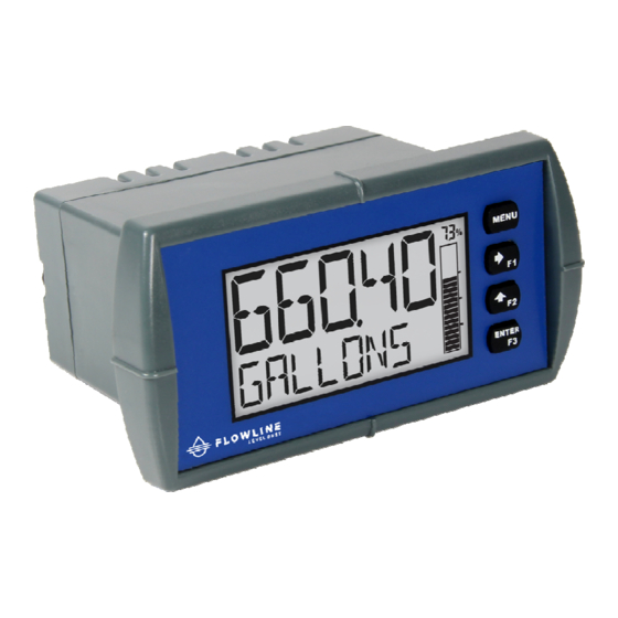
- Page 8 FRONT PANEL OPERATION Display The display shows the units for the level or volume of the tank. It also displays the unit of measurement for the application. A graphical representation of the percent full is displayed along the side of the screen. Buttons Down the right side of the LI24 series front panel are four buttons.
- Page 9 4mA at the bottom of the tank and the 20mA will be at some known level near the top of the tank (see below). When using Flowline level transmitters, the Sensor Height setting will place 4mA at the bottom or Zero level. The 20mA will be the Fill-Height setting.
- Page 10 B. Select the Decimal Points Location The decimal point may be set to as many as five decimal places. Use the Decimal Point feature to position the decimal point for all values displayed. Placement of the Decimal Point can influence the displayed output of your process.
- Page 11 C. Select the Units of Operation The LI24 series can show various engineering units in groups such as Volume, Height, Temperature, Pressure, Weight, Rate or Custom. This quick start will focus on Volume and Height. The other units will be covered in the product manual. Volume can be display in Gallons, Liters, Imperial Gallons, Cubic Meters, etc.
- Page 12 D. SCALE THE 4-20MA INPUT The 4-20 mA input can be scaled to the appropriate values for a given application. The 4-mA input (input 1) should have a corresponding display value (display 1) which represents the low end of the process value range being measured by the transmitter.
- Page 13 Arrow to move to the next digit. c. If you are reading the height of the liquid, this value will typically be the same value as the Fill-Height setting in the Flowline transmitter. d. If you 11) Press ENTER to save the Display 2 setting and to bring up SAVE? screen.
- Page 14 E. Adjust the Bar Graph The LI24 series can show various engineering units in groups such as Volume, Height, Temperature, Pressure, Weight, Rate or Custom. This quick start will focus on Volume and Height. The other units will be covered in the product manual. The LI24 Series comes equipped with a bar graph display for applications where a visual representation of the process variable’s percentage of full scale is desirable.
- Page 15 This Page Intentionally Left Blank LIN6606QS_FL_A 02/19 QS302110A...
-
Page 16: Warranty
PERSON IS AUTHORIZED TO MAKE ANY OTHER WARRANTIES OR REPRESENTATIONS ON BEHALF OF FLOWLINE. This warranty will be interpreted pursuant to the laws of the State of California. If any portion of this warranty is held to be invalid or unenforceable for any reason, such finding will not invalidate any other provision of this warranty.
Need help?
Do you have a question about the DataLoop LI24 Series and is the answer not in the manual?
Questions and answers