Table of Contents
Advertisement
Quick Links
Da
ataL
Loop
Loop
p-Powered
d Meters
LI23 In
nstruction
n Manual
• 4-
20 mA Inpu
ut
• Lo
oop-Powere
ed Process
• 1.5
5 Volt Drop
p (4.5 Volt D
• Lo
oop-Powere
ed Backligh
• NE
EMA 4X, IP
P65 Front
• -4
0 to 167°F
(-40 to 75°
• 5-
Digit Alpha
anumeric To
• 8-
Digit Alpha
anumeric Bo
• 20
0-Segment
Bargraph w
• Co
onformal Co
oated PCB
• Tw
wo Open Co
ollector Ou
• Op
ptional Loo
p-Powered
• Op
ptional 4-20
0 mA Analo
• Re
elay Pump
Alternation
• Di
splay Relay
y Runtime a
Flowline,
, Inc. | 10500
0 Humbolt S
p 562.5
98.3015 f
562.431.85
™
Meter
Drop with B
Backlight)
ht with Red
Backlight fo
C) Operatin
ng Tempera
op Line
ottom Line
with Numer
ic Percent
s for Dust &
& Humidity
tputs Stand
dard
Solid-State
e Relays
og Output
n Based on
Level and
and Cycle C
Count
Street, Los A
Alamitos, CA
507 w flow
wline.com
or Alarm Co
onditions
ature Rang
ge
Indication
Protection
Runtime
A 90720
MN
LIM
M6602FL R
Rev A
N302100 R
Rev 3
Advertisement
Table of Contents
Troubleshooting

Related Manuals for FlowLine DataLoop LI23-1001


Summary of Contents for FlowLine DataLoop LI23-1001
- Page 1 Alternation n Based on Level and Runtime • Di splay Relay y Runtime a and Cycle C Count Flowline, , Inc. | 10500 0 Humbolt S Street, Los A Alamitos, CA A 90720 M6602FL R Rev A p 562.5 98.3015 f 562.431.85...
- Page 2 Instruction Manual Disclaimer The information contained in this document is subject to change without notice. Flowline makes no representations or warranties with respect to the contents hereof and specifically disclaims any implied warranties of merchantability or fitness for a particular purpose.
-
Page 3: Table Of Contents
DataLoop™ LI23 Loop-Powered Process Meter Instruction Manual Table of Contents Table of Contents ----------------------------------------- 3 Scaling the 4-20 mA Input ......... 21 Setting the Display Features (DISPLAY) ...... 21 Table of Figures ------------------------------------------- 3 Changing the Units (UNITS) ........21 ... -
Page 4: Introduction
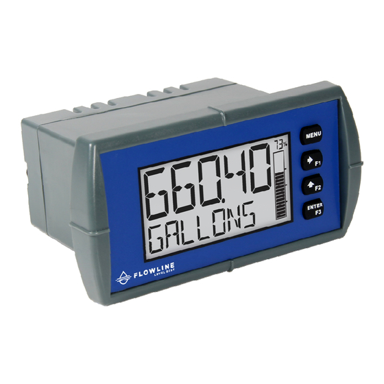
DataLoop™ LI23 Loop-Powered Process Meter Instruction Manual Introduction These loop-powered 1/8 DIN digital panel meters can be installed virtually anywhere to provide conven- ient and informative display of any 4-20 mA signal. One of the most convenient features of these instru- ments is their dual line display which is typically used to display the process variable on the 5-digit alpha- numeric top line and the units or a tag on the 8-digit alphanumeric bottom line. -
Page 5: Dataloop™ Li23 Loop-Powered Process Meter
DataLoop™ LI23 Loop-Powered Process Meter Instruction Manual Ordering Information LI23 – General Purpose Part Number Description LI23-1001 Loop-Powered, General Purpose, Bargraph, No Options LI23-1011 Loop-Powered, General Purpose, Bargraph, 4-20 mA Analog Output LI23-1201 Loop-Powered, General Purpose, Bargraph, Two Solid State Relays LI23-1211 Loop-Powered, General Purpose, Bargraph, Two Solid State Relays and 4- 20 mA Analog Output... -
Page 6: Specifications
DataLoop™ LI23 Loop-Powered Process Meter Instruction Manual Specifications Except where noted all specifications apply to operation at +25°C. Underrange Top: -9999; Bottom: -9,999,999 (flashing) Input General Input 4-20 mA Accuracy ±0.02% of span ±1 count, Square root and Environmental Operating temperature range: programmable exponent: 10-100% FS -40 to 75°C for safe area products Voltage Drop... -
Page 7: Common Open Collector & Relay (Alarm) Specifications
DataLoop™ LI23 Loop-Powered Process Meter Instruction Manual Common Open Collector & Relay (Alarm) Solid State Relays Specifications Rating 250 VAC/VDC @ 1A resistive High or Low User programmable for high or low alarm Alarm 75VA; 250VAC; 0.6A pilot duty (inductive) – UL Code D300 Alarm Deadband 0-100% FS, user programmable... -
Page 8: Safety Information
DataLoop™ LI23 Loop-Powered Process Meter Instruction Manual Safety Information CAUTION: Read complete in- WARNING: Risk of electric structions prior to installation shock or personal injury. and operation of the meter. Warning! Hazardous voltages exist within enclosure. Installation and service should be performed only by trained service personnel. -
Page 9: Panel Mounting Instructions
DataLoop™ LI23 Loop-Powered Process Meter Instruction Manual Panel Mounting Instructions Prepare a standard 1/8 DIN panel cutout – 3.622" x 1.772" (92 mm x 45 mm). Refer to Figure 1 be- low, for more details. Clearance: allow at least 4.0" (102 mm) behind the panel for wiring. ... -
Page 10: Connections
DataLo oop™ LI2 23 Loop-P Powered Process Meter nstruction Ma anual Conne ections All co nnections are e made to rem movable screw w terminal co onnectors loca ated at the rea ar of the mete This s section is only y intended for r LI23 safe ar rea installation... -
Page 11: Current Loop (4-20 Ma) Connections
DataLoop™ LI23 Loop-Powered Process Meter Instruction Manual Current Loop (4-20 mA) Connections Signal connections are made to a six-terminal connector labeled SIGNAL on Figure 4. The following fig- ures show a 4-20 mA current loop connected to the meter. The first figure shows the connection without the backlight and the second shows the connection with the backlight (the backlight can be disa- bled/enabled in the SYSTEM menu). -
Page 12: 4-20 Ma Output Connections
DataLoop™ LI23 Loop-Powered Process Meter Instruction Manual 4-20 mA Output Connections Connections for the 4-20 mA transmitter output are made to the connector terminals labeled mA OUT. The 4-20 mA output must be powered from an external power supply. Figure 8. 4-20 mA Output Connections Solid State Relay Connections Relay connections are made to a four-terminal connector labeled SSR1 and SSR2 in Figure 4. -
Page 13: Open Collector Outputs
DataLoop™ LI23 Loop-Powered Process Meter Instruction Manual Open Collector Outputs Open collector output 1 and 2 connections are made to terminals labeled O1+ and O1-, and O2+ and O2-. Connect the alarm or pulse input device as shown below. Figure 10. Open Collector Output Connections MN302100 Rev 3... -
Page 14: Setup And Programming
DataLo oop™ LI2 23 Loop-P Powered Process Meter nstruction Ma anual Setup p and Pro ogramm ming e meter is fact tory calibrate d prior to ship pment to disp play 0 to 100, ich correspon nds to the 4-2 0 mA input. -
Page 15: Display Functions & Messages
DataLoop™ LI23 Loop-Powered Process Meter Instruction Manual Display Functions & Messages The meter displays various functions and messages during setup, programming, and operation. The following table shows the main menu functions and messages in the order they appear in the menu. Parameter Action/Setting Description Parameter... - Page 16 DataLoop™ LI23 Loop-Powered Process Meter Instruction Manual Parameter Action/Setting Description Parameter Action/Setting Description Program the open collector for Scale or calibrate the mA input ALARM SCALE.CAL alarm output Scale the input SCALE PV Program the open collector as a ...
- Page 17 DataLoop™ LI23 Loop-Powered Process Meter Instruction Manual Parameter Action/Setting Description Parameter Action/Setting Description Start/stop relay 2 timer The software version RLY2 VER Start the selected timer output The meter model number START ...
-
Page 18: Main Menu
DataLoop™ LI23 Loop-Powered Process Meter Instruction Manual Parameter Action/Setting Description Parameter Action/Setting Description Display open collector 1 timer PV PCT (1 or 2) Display the process variable per- TIMR OC1 centage of full scale Display open collector 2 timer ... -
Page 19: Setting Up The Input Signal (Input)
DataLoop™ LI23 Loop-Powered Process Meter Instruction Manual Setting Up the Input Signal (INPUT) It is very important to read the following information, before proceeding to program the meter: The meter is factory calibrated prior to shipment to display 0-100 gallons, which corresponds to the 4- 20 mA input. -
Page 20: Available Unit Classes And Units
DataLoop™ LI23 Loop-Powered Process Meter Instruction Manual Available Unit Classes and Units The meter has six available preprogrammed unit classes, volume , height , temperature , pressure , weight , and rate . Each unit class has the following available units to choose from: Volume Units (VOLUME) Pressure Units (PRESSURE) Rate Time Bases (TIME) -
Page 21: Scaling The 4-20 Ma Input
DataLoop™ LI23 Loop-Powered Process Meter Instruction Manual Scaling the 4-20 mA Input The 4-20 mA input can be scaled to the appropriate values for a given application. The 4-mA input (input 1) should have a corresponding display value (display 1) which represents the low end of the process value range being measured by the transmitter. -
Page 22: Changing What Is Displayed (Top And Bottom)
DataLoop™ LI23 Loop-Powered Process Meter Instruction Manual Changing What is Displayed (TOP and BOTTOM) The two display lines ( Top and Bottom ) can be programmed to display different values. Use the Top and Bottom menus to make these changes. Additional menus are available if the meter is in dual-scale mode to allow the second PV to be displayed on either the top or bottom line. -
Page 23: Programming The Bargraph
DataLoop™ LI23 Loop-Powered Process Meter Instruction Manual Programming the Bargraph The LI23/4 comes equipped with a bargraph display for applications where a visual representation of the process variable’s percentage of full scale is desirable. This feature can be enabled or disabled using the Bargraph menu ( BARGRAPH ). - Page 24 DataLoop™ LI23 Loop-Powered Process Meter Instruction Manual Ordering Information on page 5 for details. SETUP OUTPUT OPEN COLLECTR RELAY 4-20 mA CONTROL 4-20 CTRL OC.OUT RELAY OUTPUT1 OUTPUT1 4-20 CTRL OC.OUT RELAY RETRANS OUTPUT2 OUTPUT2 4-20 CTRL RELAY DISABLE RELAY1 INFO CTRL RELAY2...
-
Page 25: Open Collector Outputs (Open Collectr)
DataLoop™ LI23 Loop-Powered Process Meter Instruction Manual Open Collector Outputs (OPEN COLLECTR) The meter is equipped with two NPN open collector outputs that may be set up for pulse outputs, alarms, timed pulses, or disabled. Pulse outputs can be set to transmit the PV value (PV1 or PV2 if meter is in dual-scale mode). Output 2 may be used to generate a quadrature output based on the other open collector output. - Page 26 DataLoop™ LI23 Loop-Powered Process Meter Instruction Manual Pulse (PULSE) Pulse outputs may be assigned to output the PV at a programmable factor. The factor determines the number of pulses per second which should be generated per unit of measure. For example, if the meter display shows 100 gallons and the factor is set to 2, the number of pulses generated per second would be 200.
- Page 27 DataLoop™ LI23 Loop-Powered Process Meter Instruction Manual Alarm (ALARM) Alarm outputs may be assigned to the PV or the digital input. When assigned to the PV, the alarm may be set as either a high alarm or a low alarm. Alarm actions ( AUTO , AUTO.MAN , LATCH , L‐CLEAR ) determine how and when the alarm should be reset.
- Page 28 DataLoop™ LI23 Loop-Powered Process Meter Instruction Manual Timer (TIMER) The timer output may be set to generate the timed pulse only once ( ONESHOT ) or continuously ( CONT ). The timer output produces a constant width pulse at a constant frequency, if set as continuous timer. Program the Off Delay ( OFF.DLAY ) from 1 second to 99 hours 59 minutes and 59 seconds.
-
Page 29: Solid State Relay Outputs (Relay)
DataLoop™ LI23 Loop-Powered Process Meter Instruction Manual Solid State Relay Outputs (RELAY) The meter is optionally equipped with two solid state relays that may be set up for alarms, timer, or pump control. Alternatively, they may be disabled. Alarms are available based on the PV value or the digital input. The alarm status will show on the display even if the output is not wired. - Page 30 DataLoop™ LI23 Loop-Powered Process Meter Instruction Manual Alarm (ALARM) Alarm outputs may be assigned to the PV or the digital input. When assigned to the PV, the alarm may be set as either a high alarm or a low alarm. Alarm actions ( AUTO , AUTO.MAN , LATCH , L‐CLEAR ) determine how and when the alarm should be reset.
- Page 31 DataLoop™ LI23 Loop-Powered Process Meter Instruction Manual Pump Control (PUMPCTRL) The pump control output is used in situations where the relays are used to control pumps. There are two options available for controlling pumps: on-off ( ON‐OFF ) and pump alternation ( ALTERN ). ON‐OFF will turn the relay on at a programmed on point and off at a programmed off point.
- Page 32 DataLoop™ LI23 Loop-Powered Process Meter Instruction Manual Pump Alternation (ALTERN) Pump alternation sets the two relays to alternate every time the first on point ( ON 1 ) is reached. The active relay will turn off once the first off point ( OFF 1 ) is reached. If the PV reaches the second on point ( ON 2 ), the other relay will also turn on.
- Page 33 DataLoop™ LI23 Loop-Powered Process Meter Instruction Manual Pump Alternation Example The following is an example application where the relays are programmed for pump alternation. Set and Reset Point Programming Relay On Point Off Point Function 7000 1000 Controls backup pump 6000 1000 Controls main pump The following graphics provide a visual representation of a typical pump alternation application:...
- Page 34 DataLoop™ LI23 Loop-Powered Process Meter Instruction Manual Timer (TIMER) The timer output may be set to generate the timed pulse only once ( ONESHOT ) or continuously ( CONT ). The timer output produces a constant width pulse at a constant frequency, if set as continuous timer. Program the Off Delay ( OFF.DLAY ) from 1 second to 99 hours 59 minutes and 59 seconds.
-
Page 35: Ma Output (4-20 Ma)
DataLoop™ LI23 Loop-Powered Process Meter Instruction Manual Relay Information (INFO) The relay information menu shows run times and cycle counts for each relay. These values may be cleared at any time by selecting the Clear option ( CLEAR? ). Flashes Flashes Momentarily Momentarily... -
Page 36: Advanced Features Menu (Advanced)
DataLoop™ LI23 Loop-Powered Process Meter Instruction Manual Advanced Features Menu (ADVANCED) To simplify the setup process, functions not needed for most applications are located in the Advanced Features menu. The options under advanced features include: advanced PV setup , cutoff , filter , pass- word , function key programming , and system settings . -
Page 37: Advanced Process Variable Setup (Adv Pv Setup)
DataLoop™ LI23 Loop-Powered Process Meter Instruction Manual Advanced Process Variable Setup (ADV PV SETUP) The Advanced PV Setup menu contains options to apply signal input conditioning functions to the input and scale/calibrate the input signal. PV SETUP *Available for PV2 only. FUNCT FUNCT FUNCT FUNCT... -
Page 38: Low-Flow Cutoff (Cutoff)
DataLoop™ LI23 Loop-Powered Process Meter Instruction Manual Setting Up the Input Signal ( INPUT ) on page 19 for details about scaling the meter. Calibrating the Input (CAL) To scale the meter without a signal source, refer to Setting Up the Input Signal ( , page 19. -
Page 39: Noise Filter (Filter)
DataLoop™ LI23 Loop-Powered Process Meter Instruction Manual The cutoff value may be programmed from 0 to 999999.9. The meter will display zero below the cutoff value. The cutoff may also be disabled to display negative values. Noise Filter (FILTER) The noise filter is available for unusually noisy signals that cause an unstable process variable display. The noise filter averages the input signal over a certain period. -
Page 40: Programmable Function Keys User Menu (User)
DataLoop™ LI23 Loop-Powered Process Meter Instruction Manual Programmable Function Keys User Menu (USER) The User menu allows the user to assign the front panel function keys F1, F2, and F3, and the digital in- put (a digital input located on the signal input connector) to access some of the menus or to activate cer- tain functions immediately (e.g. -
Page 41: Changing System Settings (System)
DataLoop™ LI23 Loop-Powered Process Meter Instruction Manual Enabling the Function Key Hint Feature (HINT) Enabling the function key hint feature will cause a hint message to be displayed when pressing the F1, F2, or F3 function keys. This text gives a brief description of what the button is programmed to do. Press- ing that function key a second time will execute that action. - Page 42 DataLoop™ LI23 Loop-Powered Process Meter Instruction Manual Calibrating the Internal mA Reference (ICAL) The meter is factory calibrated prior to shipment to display 0 to 100, which corresponds to the 4-20 mA input. The calibration equipment is traceable to NIST standards. The use of calibrated signal sources is necessary to calibrate the internal source of the meter.
-
Page 43: Meter Operation
DataLo oop™ LI2 23 Loop-P Powered Process Meter nstruction Ma anual Meter r Operat The mete r is capable o of accepting a a 4-20 mA cur rrent signal an nd displaying it in enginee ring units from -9,999 to 99,999 on the e top line or fr rom -9,999,99... -
Page 44: Troubleshooting
DataLoop™ LI23 Loop-Powered Process Meter Instruction Manual Troubleshooting Due to the many features and functions of the meter, it’s possible that the setup of the meter does not agree with what an operator expects to see. If the meter is not working as expected, refer to the recommendations below. Reset Meter to Factory Defaults When the parameters have been changed in a way that is difficult to determine what’s happening, it might be better to start the setup process from the factory defaults. -
Page 45: Factory Default Settings
DataLoop™ LI23 Loop-Powered Process Meter Instruction Manual Factory Default Settings The following table shows the factory setting for most of the programmable parameters on the meter. Parameter Display Default Setting Parameter Display Default Setting Pump Ctrl On Input Menu 0 seconds DELAY ON ... -
Page 46: Troubleshooting Tips
DataLoop™ LI23 Loop-Powered Process Meter Instruction Manual Troubleshooting Tips Symptom Check/Action 1. Check that the 4-20 mA current loop is providing No display at all at least 3.5 mA to the meter. 2. Check that the voltage drop of all devices con- nected to the 4-20 mA current loop does not ex- ceed the max rating of the loop power supply. - Page 47 DataLoop™ LI23 Loop-Powered Process Meter Instruction Manual This Page Intentionally Left Blank MN302100 Rev 3...
-
Page 48: Warranty
Flowline where: 1) there is evidence of a potentially hazardous material present with the prod- uct; or 2) the product has remained unclaimed at Flowline for more than 30 days after Flowline has duti- fully requested disposition. This warranty contains the sole express warranty made by Flowline in connec- tion with its products.
Need help?
Do you have a question about the DataLoop LI23-1001 and is the answer not in the manual?
Questions and answers