Table of Contents
Advertisement
Quick Links
Advertisement
Table of Contents

Related Manuals for FlowLine DeltaSpan LD30 Series


Summary of Contents for FlowLine DeltaSpan LD30 Series
- Page 1 DeltaSpan™ General Purpose External Mount Pressure Level Transmitter LD30 Series Manual Cable Series Conduit Series (LD30‐S_01) (LD30‐S_11) Flowline, Inc. 10500 Humbolt Street Los Alamitos, CA 90720 Tel: (562) 598‐3015 Fax: (562) 431‐8507 www.flowline.com Rev B MN301030 1 of 14 ...
-
Page 2: Table Of Contents
INTRODUCTION / TABLE OF CONTENTS Step One The LD30 Series Industrial Pressure Transmitters converts a single positive pressure into a standard 4‐20 mA output signal. The transmitter can be used to accurately measure compatible gases and liquids with full scale accuracy of 0.25%. Designed for industrial environments with a NEMA 4X (IP66) housing, this transmitter resists most effects of shock and vibration. CAUTION: Do not exceed specified supply voltage ratings. Permanent damage not covered by warranty will result. This device is not designed for 120 or 240 volt AC operation. Use only on 13 to 30 VDC. Table of Contents Specifications .............................. 3 Dimensions .............................. 4 Technology ............................ 4 Material Compatibility ........................ 4 ... -
Page 3: Specifications
SPECIFICATIONS Step Two Service: Compatible gases or liquids Wetted Materials: Body: 316 SS, 316L SS Accuracy: ±0.25% of full scale Temperature Limit: F: 0° to 200° C: ‐18° to 93° Compensated Temperature Range: F: 0° to 175° C: ‐18° to 79° Thermal Effect: Less than ±0.02%/°F. Pressure Limit: ‐S0_1: 10 psig (maximum) / 50 psig (over pressure) ‐S2_1: 30 psig (maximum) / 150 psig (over pressure) ‐S4_1: 60 psig (maximum) / 300 psig (over pressure) Power Requirement: 13 to 30 VDC Output Signal: 4 to 20 mA, 2‐wire Response Time: 50 ms Max. Loop Resistance: 1300 Ohms @ 30 VDC Current consumption: 38 mA (maximum) Electrical Connections: ‐S_01: Cable (9’ length) ‐S_11: Conduit Housing with Terminal Block Process connection: ¼” male NPT Enclosure rating: NEMA 4X (IP 66) Mounting Orientation: Mount in any position Weight: 10 oz. (283 g) ... -
Page 4: Dimensions
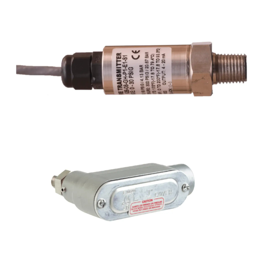
DIMENSIONS Step Three Technology: A pressure transmitter is installed near or on the bottom of the tank by way of a ¼” NPT thread. A stainless steel pressure diaphragm within the pressure transmitter is exposed on one side to the application fluid. The amount of pressure applied to the sensing surface will slightly deflect the diaphragm. The deflection of the diaphragm is measured by a built‐in microprocessor that provides greater linearity correction over common thermal compensation methods. A 4‐20 mA current signal proportional the height of the liquid or the pressure of the gas is generated from the microprocessor. Cable Series (LD30‐S_01) Conduit Series (LD30‐S_11) Material Compatibility: The LD30 series is made of 316 Stainless Steel (316 SS), 316L Stainless Steel (316L SS). The Cable Version (LD30‐S_01) is provided with 3’ (0.91 m) of cable. The Conduit Version (LD30‐S_11) is provided with a junction box (including a terminal strip) and a ½’ NPT conduit. ... -
Page 5: Safety Precautions
Flammable, Explosive and Hazardous Applications: DO NOT USE THE DELTASPAN, LD30 SERIES LEVEL TRANSMITTER IN HAZARDOUS LOCATIONS. Make a Fail‐Safe System: Design a fail‐safe system that accommodates the possibility of transmitter failure or battery power loss. In critical applications, Flowline recommends the use of redundant backup systems and alarms in addition to the primary system. ... -
Page 6: Components
COMPONENTS Step Five DeltaSpan is offered in six different models, based upon pressure rating and material. Depending on the model purchased, you may or may not have been shipped all the components shown below. DeltaSpan™ General Purpose External Mount Pressure Level Transmitter Part Maximum Range in Interface/ Number Pressure Water Column Connection LD30‐S001 9’ (2.7 m) Cable 05 psi 11.54 ft wc / 3.52 m wc LD30‐S011 Terminal Block in Housing LD30‐S201 9’ (2.7 m) Cable 15 psi 34.63 ft wc / 10.56 m wc LD30‐S211 Terminal Block in Housing LD30‐S401 9’ (2.7 m) Cable 30 psi 69.30 ft wc / 21.12 m wc LD30‐S411 Terminal Block in Housing Quick Start Guide ... -
Page 7: Getting Started
GETTING STARTED Step Six The LD30 series will be installed near the bottom of the vessel. The switch can be installed through the side wall or through the bottom. Please note that the physical location of the level transmitter will indicate the lowest level of measurement within the tank. For example: mounting the transmitter 1 foot from the bottom of the tank, then the lowest reading of liquid will be 1 foot from the bottom. Note: When installing the LD30 series, design an installation method where the unit can be removed without having to remove the fluid from the vessel. The use of valves between the transmitter and the vessel can allow transmitter removal without draining the fluid. How to convert Pressure into Liquid Height? Pressure transmitters are all defined by the pressure range and not by Liquid Height. To convert pressure to Liquid Height, use the following ratio: 1 psi = 2.31 feet of water or 1 psi = 0.704 meters of water Therefore, a 15 psi transmitter will have a Liquid Height = 34.65 feet (10.56m): 15 psi x 2.31’/psi = 34.65’ or 15 psi x 0.704 m/psi = 10.56m With the above ratio, you can always find the Liquid Height or water column (wc) of any pressure transmitter. Rev B MN301030 7 of 14 ... -
Page 8: How Does Specific Gravity Affect Pressure Transmitters
GETTING STARTED (continued) Step Six How does Specific Gravity affect pressure transmitters? The Specific Gravity (SG) of a liquid will not change the pressure of the transmitter, but will affect how the transmitter reads the liquid height. Remember, liquids with a SQ < 1.0 are lighter than water and liquids with a SG > 1.0 are heavier than water. Water has a SG = 1.0. A SG < 1.0 requires more liquid (a taller water column) to equal the same pressure as with water. A SG > 1.0 requires less liquid (shorter water column) to equal the same pressure as with water. SG = 0.9 SG = 1.0 SG = 1.2 To calculate the Maximum Liquid Height of a sensor, use the following formula: ... -
Page 9: How To Select The Correct Pressure Transmitter
GETTING STARTED (continued) Step Six How to select the correct pressure transmitter? The objective is to select a sensor with an operational range that will cover the entire application span. If the liquid height of the tank is above the sensor’s Maximum Liquid Height, then the sensor will not be able to read a full tank level. Compare the tank’s Pressure @ Full against the sensor’s pressure range to select a sensor. ... -
Page 10: How To Configure A Panel Meter When A Pressure Transmitter Is Used
GETTING STARTED (continued) Step Six How to configure a panel meter when a pressure transmitter is used? This method works with the LI55 series, LI25 Series, LI10 Series and LI50 Series. These panel meters are configured using the SCALE function. The SCALE function typically has four settings. These settings are as follows: ... -
Page 11: Electrical Installation
ELECTRICAL INSTALLATION Step Seven Wiring: An external power supply delivering 13‐30 VDC with minimum current capability of 40 mA DC (per transmitter) is required to power the control loop. See Figure A below for connection of the power supply, transmitter and receiver. The range of appropriate receiver load resistance (RL) for the DC power supply voltage available is expressed by the formula: RLmax = (Vsup – 10V) / 20 mA DC Shielded cable is recommended for control loop wiring. Use the Red wire / (1) terminal as the (+) and the Black wire / (2) terminal as the (‐). Fig. A Connections Cable Version (LD30‐S_01 Series) Conduit Version (LD30‐S_11 Series) (+) = Red Wire & (‐) = Black Wire (+) = Terminal #1 & (‐) = Terminal #2 ... -
Page 12: Installation
INSTALLATION Step Nine The LD30 series is designed to operate with only the installation thread being exposed to the fluid. Avoid installing the level transmitter along the bottom of the tank as materials such as sludge will build up and coat/cover the port. ... -
Page 13: Maintenance
MAINTENANCE Step Ten Maintenance should consist of inspection to see that the transmitter is free from debris and not coated with any substance, which would prevent liquid from freely entering and leaving the transmitter. If this occurs, the transmitter should be cleaned. Cleaning procedure: 1. Power: Make sure that all power to the transmitter, controller and/or power supply is completely disconnected. 2. Transmitter removal: If necessary, make sure that the tank is drained well below the switch prior to removal. Carefully, remove the transmitter from the installation. 3. Cleaning the switch: Using a soft bristle brush and mild detergent, carefully wash the switch. Do not use harsh abrasives such as steel wool or sandpaper, which might damage the surface of the sensor. Do not use incompatible solvents, which may damage the sensor's stainless steel body. Take particular care to remove any scaling from the body and that there is no debris inside the inlet. Transmitter installation: Follow the appropriate steps of installation as outlined in the Installation section of this manual. Testing the transmitter: First, verify that the sensor is wired correctly. Next, check if the power supply is providing the required power. Finally confirm that the loop resistance is not exceeding the sensor’s specification. If transmitter is not functioning properly, isolate the transmitter from the system and wire as shown below. ... -
Page 14: Warranty, Returns & Limitations
Step Eleven Warranty Flowline warrants to the original purchaser of its products that such products will be free from defects in material and workmanship under normal use and service in accordance with instructions furnished by Flowline for a period of two years from the date of manufacture of such products. Flowline's obligation under this ...
Need help?
Do you have a question about the DeltaSpan LD30 Series and is the answer not in the manual?
Questions and answers