
Subscribe to Our Youtube Channel
Related Manuals for Qlima TS27


Summary of Contents for Qlima TS27
- Page 1 SPLIT UNIT AIR CONDITIONER TS 27 OPERATING MANUAL ISTRUZIONI D’USO > GEBRUIKSAANWIJZING INSTRUKCJA OBSŁUGI...
- Page 2 Dear Sir, Madam, Congratulations on the purchase of your airconditioner. You have acquired a high quality product that, if used responsibly, will give you many years of pleasure. Please read these instructions for use first in order to ensure the maximum life span of your airconditioner. On behalf of the manufacturer, we provide a 24-month guarantee on all material and production defects.
-
Page 3: Table Of Contents
CONTENTS Specifications page Parts page Before use page Installation instructions page Instructions for use page Maintenance page Protection page Problem solving page Guarantee conditions page... -
Page 4: A Specifications
SPECIFICATIONS To be used as indication, subject to modifications. Model TS27 Cooling capacity * kW (BTU/h) 2.7 (9,000) EE Class Heating capacity kW (BTU/h) 2.8 (9,500) COP Class Dehumidification capacity ** Ltr/day Power consumption cooling 0.88 Power consumption heating 0.88... -
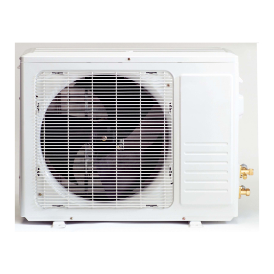
Page 5: B Parts
PARTS INDOOR UNIT Air inlet Front panel Emergency button Display Air outlet Vertically adjustable vane Horizontally adjustable vane Active carbon filter (optional) Healthy air filter (optional) Air filter Remote control OUTDOOR UNIT Air inlet Drainage hose Note: Condensation is drained during COOLING or DRYING Pipes and power cable... -
Page 6: C Before Use
If you do not press any button within 10 seconds, the remote control is automatically preset to the heat pump. Type TS27 is fitted with a heat pump. The Heat function can NOT be adjusted with the remote control when the remote control has been preset to Cool Only. -
Page 7: D Installation Instructions
INSTALLATION INSTRUCTIONS Installation diagram Distance to the ceiling must be Distance to the wall a minimum of 50 mm. must be a minimum of 50 mm. Distance to the wall must be a minimum of 50 mm. Distance between the air inlet and the wall must be Distance between a minimum of 250 mm. - Page 8 Connecting the power cable Front panel Wiring between the indoor and outdoor unit: Remove the plastic cover from the indoor unit. Use the circuit diagram (attached to the indoor unit) as Connecting clamp (inside) a reference for the connections. Replace the cover, “B” on the outside. Select the correct location No obstacles in the vicinity of the air outlet.
- Page 9 INSTALLATION OF THE INDOOR UNIT Installing the mounting plate Fit the mounting plate at the location where the indoor unit will be hung. Take account of the direction of the pipes. Place the mounting plate horizontally with the aid of a level indicator or plumb line. Drill holes with a depth of 32 mm in order to mount the plate.
- Page 10 Connect the indoor unit pipes with two nut spanners. Select the correct tightening moment in order to prevent the pipes, con- necting pieces and nuts from being deformed or damaged. First tighten by hand, and then with nut spanners. Tightening Model Pipe dimensions moment size TS27 TS27...
- Page 11 Check that all wiring is securely connected. Install an earth leak switch. Note: All cables used must be approved in accordance with local regulations. Cable specifications Power cable Power cable connection Power cable connection 1 (heat pump) Type Cross-section Type Cross-section Type Cross-section TS27...
- Page 12 OUTDOOR UNIT INSTALLATION Fit the drainage outlet and drainage hose (only for models with a heat pump). Condensation will drip off the outdoor unit when the indoor unit is operating in Heating mode. Fit a drainage outlet and a drainage hose in order to drain the water effectively.
- Page 13 Unscrew the two-way and three-way valve and remove the covers. Unscrew the supply pipe and remove the cover. Connect the flexible hose of the vacuum pump to the supply pipe. Allow the vacuum pump to operate for 10-15 minutes until a pressure of 10 mmHg absolute is achieved.
-
Page 14: E Instructions For Use
INSTRUCTIONS FOR USE Operation and display POWER INDICATOR Lights up when power supply is connected. SLEEP MODE INDICATOR Lights up when this function is activated. RECEIVER Receives the signal from the remo- te control. TIME INDICATOR Lights up during preset time. OPERATING INDICATOR Lit when the unit is in operation. - Page 15 Remote control The remote control transmits signals to the system. UP button (TOO COLD button) To raise your preset room temperatu- re and extend time periods. FAN SPEED operation button SLEEP button For the selection of the ventilator speed in the To activate or deactivate the sleep mode.
- Page 16 OPERATING INSTRUCTIONS FEEL mode operating procedure The operating mode is selected automatically (HEATING, DRY, FAN, COOLING), depending on the room temperature at the time the selection takes place. With the remote control pointed at the air conditioner. Activation Press the ON/OFF/RUN button. The RUN indicator on the indoor unit will light up when the machine receives a signal.
- Page 17 ADJUSTING THE TIMER To activate the air conditioner at the desired time, follow the procedure specified below (the remote control and air conditioner are switched off): Press the Timer button. Select the desired mode by pressing the Mode button. Select the desired temperature by pressing the button (only possible when the ‘cool’...
-
Page 18: F Maintenance
MAINTENANCE Cleaning the front panel Switch the machine off and remove the plug from the socket. Hold the front panel at position “a” and pull it towards you. Clean with a soft dry cloth. Use lukewarm water (max. 30˚ C) to remove stubborn dirt. Never use volatile substances, such as benzene, or abrasives to remove dirt. - Page 19 Warning If the air conditioner is operating in the COOLING or DRY mode while relative humidity is over 80%, moisture may drip out of the air outlet of the indoor unit (due to a window or door being open, for instance). Noise Install the air conditioner on a solid base in order to prevent excessive noise.
-
Page 20: H Problem Solving
PROBLEM SOLVING The following problems do not always indicate a fault. Please check them before contacting the service department: Problem Cause / Solution The plug is not inserted firmly in the socket. The unit does not operate. The batteries in the remote control are empty. The safety feature has been activated or the fuse has burnt out. -
Page 21: I Guarantee Conditions
GUARANTEE CONDITIONS There is a 24-month guarantee on the air conditioner from the purchase date. Within this period, all material and manufacturing defects will be repaired free of charge. The following rules will apply: • We expressly reject all further claims to damage compensation, including claims relating to secondary damage. - Page 22 Egregio Signore, Gentile Signora, Ci congratuliamo con per l’acquisto del condizionatore d’aria. Lei ha acquistato un prodotto di qualità, che Le offrirà molti anni di comfort, a condizione che venga usato in modo responsabile. Per una durata ottimale del condizionatore d’aria La invitiamo a leggere le istruzioni d’uso.
- Page 23 CONTENUTO Specifiche pagina Componenti pagina Operazioni preliminari pagina Istruzioni per l’installazione pagina Istruzioni d’uso pagina Manutenzione pagina Sicurezza pagina Risoluzione dei problemi pagina Condizioni della garanzia pagina >...
- Page 24 SPECIFICHE I valori riportati sono indicativi, dati soggetti a modifiche Modello TS27 Ca. di raffreddamento* kW (BTU/h) 2,7 (9.000) EE Class Capacità di riscaldamento kW (BTU/h) 2,8 (9.500) COP Class Deumidificazione max.** L/24 h Assorbimento energia in raffreddamento 0,88 Assorbimento energia in riscaldamento...
- Page 25 IDENTIFICAZIONE DEI COMPONENTI UNITÀ INTERNA Presa d’aria Quadro frontale Pulsante di emergenza Display Uscita dell’aria Regolazione ver- ticale delle lame Regolazione oriz- zontale delle lame Filtro anti-par- ticelle di carbon attivo (optional) Filtro di sicurez- za per la tutela della salute (optional) Filtro dell’aria Telecomando...
- Page 26 Se non viene premuto alcun pulsante entro 10 secondi, il telecomando viene impostato automaticamente per la funzione “pompa di calore”. Gli apparecchi TS27 sono dotati di una pompa di calore. Impostando il telecomando per utilizzare l’apparecchio solo a fini di condizionamento, NON è possibile impostare la funzione di riscaldamento con il telecomando.
- Page 27 ISTRUZIONI PER L’INSTALLAZIONE Schema di installazione La distanza dal soffitto deve La distanza dal muro essere superiore a 50 mm. deve essere superiore a 50 mm. La distanza dal muro deve essere superiore a 50 mm. La distanza tra il La distanza tra il bocchettone di bocchettone di uscita dell’aria e il muro deve...
- Page 28 Collegamento del cavo di alimentazione Quadro frontale Connessione tra l’unità interna e l’unità esterna Rimuovere il rivestimento in plastica dell’unità interna. Per il collegamento far riferimento al diagramma dei Morsetto di collega- mento (interno) cablaggi (allegato all’unità interna). Ricollocare il rivestimento in plastica. Verificare che il lato “B”...
- Page 29 Installazione dell’unità interna Installazione del piano di supporto scegliere il punto dove collocare il piano di supporto dell’unità esterna tenendo conto della direzione dei tubi; disporre il piano di supporto orizzontal- mente con l’ausilio di una riga orizzontale o di una bolla; praticare fori di 32 mm di profondità...
- Page 30 Stringergli prima con le dita, poi utilizzare le chiavi. Ampiezza Modello Dimensione del tubo Serraggio dei dadi TS27 TS27 >...
- Page 31 NB: tutti i cavi utilizzati devono essere approvati secondo le norme locali vigenti. Specifiche cavi Cavo di alimentazione Collegamento cavo di alimentazione Collegamento cavo di alimentazione 1 (per pompa di calore) Tipo Sezione Tipo Sezione Tipo Sezione trasversale trasversale trasversale TS27 >...
- Page 32 INSTALLAZIONE UNITÀ ESTERNA Installare il portello di scarico e il tubo flessibile di scarico (solo per i modelli dotati di pompa di calore). Dall’unità esterna defluisce condensa quando è attiva la modalità riscaldamento. Installare un portello di scarico e un tubo flessibile di scarico per dirigere il flusso di acqua.
- Page 33 Svitare e rimuovere i cappucci della valvole a due e tre vie. Svitare e rimuovere il cappuccio del condotto secondario. Collegare il tubo flessibile della pompa a vuoto al condotto secondario. Avviare la pompa a vuoto e farla funzionare per 10/15 minuti, fino a raggiungere un vuoto di 10 mm Hg assoluti.
- Page 34 ISTRUZIONI D’USO Operazioni e relative indicazioni sul display SPIA LUMINOSA DI ALIMENTAZIONE La spia si illumina quando l’apparecchio è alimentato SPIA LUMINOSA DI FUNZIONE SLEEP La spia si illumina quando questa funzione è attiva RICEZIONE SEGNALE La spia si illumina quando l’apparecchio riceve un segnale dal telecomando TIMER La spia si illumina nell’orario impostato con il timer...
- Page 35 Telecomando Il telecomando invia segnali al sistema. PULSANTE UP (pulsante TOO COOL – troppo freddo) Per aumentare la temperatura ambiente impostata o l’orario nella funzione timer. PULSANTE DI REGOLAZIONE FAN SPEED PULSANTE SLEEP Per selezionare la velocità del motore della ventola Per attivare/disattivare la modalità...
- Page 36 ISTRUZIONI D’USO Procedura per il funzionamento in modalità FEEL La modalità di funzionamento (HEATING, DRY, FAN, COOLING) viene selezionata automaticamente seconda della temperatura ambiente. Puntare il telecomando verso il condizionatore. Accensione Premere il pulsante ON/OFF/RUN; quando l’apparecchio riceve il segnale, la spia RUN sull’unità interna si accende. Quando l’apparecchio non è...
- Page 37 IMPOSTAZIONE DEL TIMER Affinché il condizionatore si accenda in corrispondenza dell’orario desiderato, seguire la seguente procedura (con apparecchio e telecomando spenti): Premere il pulsante Timer. Scegliere la modalità desiderata premendo il pulsante Mode. Scegliere la temperatura desiderata premendo il pulsante (solo con selezionata la modalità...
- Page 38 MANUTENZIONE Manutenzione del quadro frontale Spegnere l’apparecchio e togliere la spina dalla presa di alimentazione. Afferrare il quadro frontale in corrispondenza della posizione “a” e tirarlo verso l’esterno. Pulire con un panno morbido asciutto. Utilizzare acqua tiepida (meno di 30°C) per pulire l’apparecchio nel caso in cui fosse particolarmente sporco. Non utilizzare mai sostanze volatili quali benzina o polveri abrasive per pulire l’apparecchio.
- Page 39 Avvertenze Quando il climatizzatore è programmato sulla funzione COOLING o DRY, in caso di umidità dell'aria relativa superiore all'80%, lo scarico dell'aria dell'unità interna può gocciolare (per il fatto che, ad esempio, sono aperte una finestra o una porta). Rumori - Installare il condizionatore su una superficie solida in modo tale da prevenire la produzione di rumori.
- Page 40 RISOLUZIONE DEI PROBLEMI I seguenti casi non corrispondono necessariamente a un malfunzionamento. Controllare sempre prima di richiedere un intervento da parte dell’assistenza. Problema Causa/Solutione L’apparecchio non funziona Spina non inserita correttamente nella presa Batterie del telecomando scariche La protezione si attiva quando il fusibile si è fulminato. Non viene erogata aria calda o Le prese d’aria e i bocchettoni di fuoriuscita dell’aria sono fredda...
- Page 41 CONDIZIONI DELLA GARANZIA Il condizionatore d’aria ha una garanzia di 24 mesi dalla data d’acquisto. Entro questo periodo vengono riparati gratuitamente tutti i difetti di materiale e di fabbricazione. Qui di seguito sono riportate le condi- zioni della garanzia: Rifiutiamo esplicitamente tutte le altre richieste di risarcimento, compresi danni conseguenti. La riparazione o la sostituzione di parti entro il termine di garanzia non comporta la proroga della garanzia stessa.
- Page 42 Geachte mevrouw, meneer, Van harte gefeliciteerd met de aankoop van uw airconditioner. U heeft een kwaliteitsproduct aangeschaft waar u nog vele jaren plezier van zult hebben, mits u de airconditioner verantwoord gebruikt. Lees daarom eerst deze gebruiksaanwijzing voor een optimale levensduur van uw airconditioner. Wij geven u namens de fabrikant 24 maanden garantie op alle optredende materiaal- en fabricagefouten.
- Page 43 INHOUD Specificaties pagina Onderdelen pagina Voor ingebruikname pagina Installatie pagina Bediening pagina Onderhoud pagina Beveiliging pagina Storingen verhelpen pagina Garantiebepalingen pagina...
- Page 44 SPECIFICATIES Indicatief gebruiken, wijzigingen voorbehouden Model TS27 Koelcapaciteit * kW (BTU/uur) 2,7 (9.000) EE Class Verwarmingscapaciteit * kW (BTU/uur) 2,8 (9.500) COP Class Ontvochtigingscapaciteit ** liter/dag Energieverbruik bij koelen 0,88 Energieverbuik bij verwarmen 0,88 Voeding Volt/Hz/Ph 220-240/50/1 Stroomsterkte /uur Maximale luchtstroom...
- Page 45 ONDERDELEN BINNENUNIT Luchtinlaat Frontpaneel Noodknop Display Luchtuitlaat Verticaal afstellen lamel Horizontaal afstellen lamellen Actief koolstof- filter (optioneel) Filter voor gezon- de lucht (optioneel) Luchtfilter Afstandsbediening BUITENUNIT Luchtinlaat Afvoerslang Opmerking: afvoer condenswater tijdens KOELEN of DROGEN Leidingen en voedingskabel Luchtuitlaat De afbeeldingen in deze gebruiksaanwijzing zijn gebaseerd op een standaardmodel. De door u gekochte airconditioner kan een ander model hebben.
- Page 46 Als u niet binnen 10 seconden op een willekeurige knop drukt, wordt de afstandsbediening automatisch op de warmtepomp ingesteld. Type TS27 is uitgerust met een warmtepomp. Wanneer de afstandsbediening op Alleen Koelen is ingesteld, kan de Verwarmingsfunctie NIET via de afstandsbediening worden ingesteld.
- Page 47 INSTALLATIE Installatieschema Afstand tot het plafond moet Afstand tot de muur minimaal 50 mm zijn. moet minimaal 50 mm zijn. Afstand tot de muur moet minimaal 50 mm zijn. Afstand tussen luchtin- laat en muur moet Afstand tussen minimaal 250 mm zijn. luchtinlaat en muur moet mini- maal 250 mm zijn.
- Page 48 Aansluiting voedingskabel Frontpaneel Bedrading tussen binnen- en buitenunit: Verwijder de kunststof kap van de binnenunit Gebruik het bedradingsschema (gehecht aan de Aansluitklem (binnenkant) binnenunit) als referentie voor aansluiting. Plaats de kap terug, “B” aan de buitenkant. Kies de juiste locatie Geen obstakels in de buurt van de luchtuitlaat, zodat de luchtstroom ongehinderd de gehele ruimte bereikt.
- Page 49 INSTALLATIE BINNENUNIT Installeren van de montageplaat Montageplaat monteren op de plaats waar de binnenunit komt te hangen, houd rekening met de richting van de leidingen. Plaats de montageplaat horizontaal met behulp van een waterpas of schietlood Boor gaten met een diepte van 32 mm om de plaat vast te zetten.
- Page 50 Verbind de binnenunit leidingen met twee moersleutels. Kies het juiste aanhaalmoment om te voorkomen dat leiding, verbindingsstukken en moeren vervormen of beschadigen. Eerst met de hand aandraaien, daarna met moersleutels vastzetten. Aanhaal- Grootte Model Afmeting leiding moment moer TS27 TS27...
- Page 51 Controleer of alle bedrading goed vastzit. Installeer een aardlekschakelaar. Opmerking: Alle gebruikte kabels dienen goedgekeurd te zijn volgens de lokaal geldende regels. Specificaties kabels Voedingskabel Aansluiting voedingskabel Aansluiting voedingskabel 1 (warmtepomp) Type Dwarsdoor- Type Dwarsdoor- Type Dwarsdoor- snede snede snede TS27...
- Page 52 INSTALLATIE BUITENUNIT Monteer afvoeruitgang en afvoerslang (alleen voor modellen met warmtepomp). Wanneer de binnenunit op de verwarmingsstand staat, drupt er condenswater van de buitenunit. Monteer een afvoeruitgang en een afvoerslang om het water probleemloos af te voeren. Monteer de afvoeruitgang en rubberen sluitring op de bodemplaat van de buitenunit (zie afbeelding).
- Page 53 De twee- en driewegklep losschroeven en de kapjes verwijderen. De aanvoerleiding losschroeven en het kapje verwijderen. De flexibele slang van de vacuümpomp aansluiten op de aanvoerleiding. De vacuümpomp 10-15 minuten laten draaien tot een druk van 10 mmHg absoluut. De lagedruk knop op de vacuümpomp sluiten terwijl de pomp nog loopt. Hierna de pomp uitschakelen.
- Page 54 BEDIENING Bediening en display STROOM INDICATIELAMPJE Licht op wanneer de stroom- toevoer aangesloten is. SLAAPSTAND INDICATIELAMPJE Licht op als deze functie actief is. SIGNAALONTVANGER Ontvangt signaal van de afstandsbediening. TIJD INDICATIELAMPJE Licht op tijdens ingestelde tijd. IN BEDRIJF INDICATIELAMPJE Brandt als unit in bedrijf is. NOODKNOP Om de unit te bedienen als de...
- Page 55 Afstandsbediening De afstandsbediening zendt signalen naar het systeem. UP KNOP (TE KOUD KNOP) Om ingestelde kamertemperatuur te verhogen en tijd te verlengen. FAN SPEED BEDIENINGSKNOP SLEEP KNOP Voor selectie ventilatorsnelheid binnenunit: Om slaapstand in te stellen of op te heffen. automatisch, hoog, medium en laag.
- Page 56 BEDIENINGSINSTRUCTIES FEEL modus bedrijfsprocedure De bedrijfsmodus wordt automatisch geselecteerd (HEATING, DRY, FAN, COOLING) afhankelijk van de kamertemperatuur op het selectiemoment. Met de afstandsbediening op de airconditioner gericht. Inschakelen Druk op de ON/OFF/RUN knop. Wanneer het apparaat een signaal ontvangt licht het RUN indicatielampje van de binnenunit op.
- Page 57 INSTELLEN TIMER Om de airconditioner op het gewenste tijdstip in te schakelen moet de volgende procedure gevolgd worden (de afstandsbediening en de airconditioner zijn uitgeschakeld): Druk op de Timer knop Kies de gewenste modus door op de Mode knop te drukken. Kies de gewenste temperatuur door op de knop te drukken (is alleen mogelijk wanneer de ‘cool’...
- Page 58 ONDERHOUD Schoonmaken frontpaneel Het apparaat uitschakelen en de stekker uit het stopcontact halen. Frontpaneel vastpakken op positie “a” en naar u toetrekken. Reinigen met een zachte droge doek. Gebruik handwarm water (max. 30˚ C) om hardnekkig vuil te verwijderen. Gebruik nooit vluchtige stoffen zoals benzine, of een schuurmiddel om vuil te verwijderen.
- Page 59 Waarschuwing Wanneer de airconditioner op de COOLING of DRY functie is ingesteld bij een relatieve luchtvochtigheid meer dan 80%, dan kan er vocht uit de luchtuitlaat van de binnenunit druppelen (doordat bijvoorbeeld een raam of deur open staat). Geluidsoverlast Installeer de airconditioner op een stevige ondergrond om geluidsoverlast te voorkomen. Installeer de buitenunit zodanig dat de buren geen geluidshinder ondervinden van de uitgeblazen lucht.
- Page 60 STORINGEN VERHELPEN Probleem Oorzaak / Oplossing De stekker zit niet goed in het stopcontact. Unit werkt niet. De batterijen van de afstandsbediening zijn leeg. De beveiliging is geactiveerd of de zekering is doorgebrand. Zijn de luchtinlaten, –uitlaten geblokkeerd? Geen gekoelde of verwarmde lucht. Is de temperatuur goed ingesteld? Is de luchtfilter verontreinigd? Als gevolg van storing (door ontlading van statische elektriciteit,...
- Page 61 GARANTIEBEPALINGEN U krijgt op de airconditioner 24 maanden garantie vanaf de aankoopdatum. Binnen deze periode worden alle materiaal- en fabricagefouten kosteloos verholpen. Hierbij gelden de volgende regels: Alle verdere aanspreken op schadevergoeding, inclusief gevolgschade wijzen wij uitdrukkelijk af. Reparatie of vervanging van onderdelen binnen de garantietermijn leidt niet tot verlenging van de garantie.
- Page 62 Szanowni Panstwo, Serdecznie gratulujemy Panstwu zakupu klimatyzatora. Oprócz chłodzenia powietrza, klimatyzator ten ma jeszcze inne funkcje, mianowicie: ogrzewanie, odwilżanie i wentylację. Nabyli Państwo produkt wysokiej jakości, który - przy prawidłowej eksploatacji – będzie Państwu dobrze służył przez wiele lat. W celu zapewnienia optymalnej jakości pracy klimatyzatora, prosimy przed pierwszym użyciem aparatu uważnie zapoznać...
- Page 63 SPIS TREŚCI Dane techniczne strona Elementy konstrukcyjne strona Środki bezpieczeństwa strona Instrukcje dot. instalacji strona Instrukcje dot. eksploatacji strona Konserwacja strona Urządzenie zabezpieczające strona Wykrywanie usterek strona Warunki gwarancji strona...
- Page 64 DANE TECHNICZNE Podane wartości są orientacyjne, z zastrzeżeniem zmian Rodzaj / typ urządzenia TS27 Moc chłodzenie * kW (BTU/h) 2,7 (9.000) EE Class Wydajność grzania kW (BTU/h) 2,8 (9.500) COP Class Osuszanie ** L/24h Zużycie prądu w czasie chłodzenia 0,88 Zużycie prądu w czasie grzania...
- Page 65 ELEMENTY KONSTRUKCYJNE SEGMENT WEWNÍTRZNY Wlot powietrza Płyta frontowa Przycisk awaryjny Wyświetlacz Wylot powietrza Pionowe płytki wentylacyjne Poziome płytki wentylacyjne Aktywny filtr węglowy (opcjonalnie) Filtr do zdrowego powietrza (opcjonalnie) Filtr powietrza Pilot SEGMENT ZEWNÍTRZNY Wlot powietrza Przewód odprowadzający* Przewody rurowe i kablowe Wylot powietrza Ilustracje zawarte w niniejszej Instrukcji Obsługi oparte są...
- Page 66 Jeżeli w ciągu 10 sekund nie naciśniesz żadnego guzika, pilot automatycznie wybierze funkcję pompy cieplnej. W pompę cieplną wyposażone są następujące typy klimatyzatora:TS27. Kiedy pilot ustawiony jest na funkcję „Tylko Chłodzenie” (Cooling Only), funkcji ogrzewania NIE można uruchomić...
- Page 67 INSTRUKCJE DOTYCZĄCE INSTALACJI Schemat instalacji. Odstęp od sufitu musi wynosić Odstęp od ściany musi minimalnie 5 cm. wynosić minimalnie 5 cm. Odstęp od ściany musi wynosić minimalnie 5 cm. Odległość między Odległość między wlotem wlotem powietrza powietrza a ścianą musi wynosić a ścianą...
- Page 68 Podłączenie kabli elektrycznych. Płyta frontowa Przewody między obydwoma segmentami klimatyzatora (wewnętrznym i zewnętrznym): Podnieś płytę frontową segmentu wewnętrznego. Zaciski podłączeń Podłącz kable zgodnie z diagramem podanym na płytce obwodu drukowanego. Dokładnie zamknij płytę (punkty ‘B” po zewnętrznej stronie). Wybierz stosowne miejsce Obudowa Naprzeciwko wylotu powietrza nie może być...
- Page 69 INSTALACJA SEGMENTU WEWNE ˛TRZNEGO Zamocowanie płyty montażowej W miejscu, gdzie zawieszony ma być segment wewnętrzny przytwierdź do ściany płytę montażową, biorąc pod uwagę kierunek poprowadzenia przewodów rurowych. Przystępując zamocowania płyty montażowej skorzystaj z poziomnicy w celu dokładnego określenia poziomu. Wywierć otwory o głębokości 32 mm. W otwory wsadź...
- Page 70 Za pomocą dwóch skrętek rurowych złącz przewody rurowe segmentu wewnętrznego. Zwróć uwagę na właściwy moment obrotowy, aby nie przemieścić i nie uszkodzić przewodów i skrętek. Najpierw przykręcić palcami, następnie za pomocą klucza.. Moment Wielkość Wymiary przewodów rurowych obrotowy skrętki TS27 TS27...
- Page 71 Sprawdź, czy wszystkie przewody są dobrze zamocowane. Zainstaluj łącznik uziomowy. Uwaga: Wszystkie przewody kablowe muszą mieć atesty zgodne z obowiązującymi w kraju przepisami. Dane techniczne przewodów kablowych Przewód zasilania Przewód łączący Przewód łączący 1 (do pompy cieplnej) Średnica Średnica Średnica TS27...
- Page 72 INSTALACJA SEGMENTU ZEWNE ˛TRZNEGO Montaż wylotu cieczy i węża odprowadzającego (tylko w typach klimatyzatora z pompą cieplną). Kiedy segment wewnętrzny pracuje na funkcji ogrzewania, z aparatu kroplami wydala się kondensat. Zamontuj wylot i wąż odprowadzający w celu bezproblemowego odprowadzenia wody. Zamontuj wylot odprowadzający i gumową...
- Page 73 Odkręć dwu- i trójdrogowy zawór i zdejmij z nich nasadki. Odkręć przewód rurowy doprowadzający powietrze i zdejmij nasadkę. Giętki wąż pompy próżniowej podłącz do przewodu doprowadzającego powietrze. Pompa próżniowa powinna pracować przez 10-15 minut, aż osiągnięte zostanie ciśnienie absolutne o wartości 10 mmHg.
- Page 74 INSTRUKCJE DOT. EKSPLOATACJI Obsługa i wyświetlacz LAMPKA KONTROLNA ZASILANIA Świeci się kiedy urządzenie podłączone jest do prądu LAMPKA KONTROLNA STANU SPOCZYNKU (PRZERWY) Świeci się kiedy ta funkcja jest włączona ODBIORNIK SYGNAłU Odbiera sygnały wysyłane z pilota LAMPKA KONTROLNA CZASOWNIKA Świeci się podczas zaprogramowanego czasu pracy LAMPKA KONTROLNA PRACY KLIMATYZATORA Świeci się...
- Page 75 Pilot Pilot wysyła do odbiornika następujące sygnały. Guzik UP (ZBYT ZIMNO) Do podwyższania temperatury w pokoju i przedłużenia czasu ogrzewania. Guzik obsługi FAN (WENTYLATOR). Do regulowania Guzik SLEEP (PRZERWA) obrotów wentylatora w segmencie wewnętrznym: Do włączania i wyłączania przerwy w pracy aparatu. automatycznie, wysokie, średnie, niskie.
- Page 76 INSTRUKCJE DOTYCZĄCE EKSPLOATACJI Funkcja podstawowa feel (czujnik) Poszczególne funkcje podstawowe (HEATING, DRY, FAN, COOLING) wybierane są automatycznie, zależnie od tego, jaką temperaturę pomieszczenia czujnik skonstatuje w momencie wybierania. Z pilotem nakierowanym na segment wewnętrzny Włączenie klimatyzatora Wciśnij guzik ON/OFF/RUN. Kiedy aparat odbierze sygnał, zapali się...
- Page 77 ZAPROGRAMOWANIE CZASOWNIKA Aby klimatyzator się włączył o określonej godzinie, wykonaj następujące czynności (zarówno pilot, jak i klimatyzator są wyłączone): Naciśnij guzik ‘Timer’ Za pomocą guzika ‘Mode’ wybierz wymaganą funkcję podstawową. Za pomocą guzika wybierz pożądaną temperaturę (jest to możliwe tylko wówczas, jeśli uprzednio wybrana została funkcja ‘cool’ albo ‘heat’). Za pomocą...
- Page 78 KONSERWACJA Czyszczenie płyty frontowej Wyłącz aparat i wyjmij wtyczkę z kontaktu. Chwyć płytę frontową w punktach „a” i przyciągnij do siebie. Wyczyść płytę miękką, suchą ściereczką. Do usunięcia uporczywego brudu możesz użyć letniej wody (poniżej 30°C). Do czyszczenia nigdy nie używaj mokrych substancji, jak benzyna czy środki ścierające.
- Page 79 OSTRZEŻENIE Jeśli klimatyzator jest ustawiony na funkcję COOLING (chłodzenie) lub DRY (osuszanie) przy wilgot- ności względnej powietrza przekraczającej 80%, z odpływu powietrza modułu wewnętrznego może kapać woda (przez to, że np. otwarte jest okno lub drzwi). Hałas Aby uniknąć wzrostu poziomu głośności, umocuj wewnętrzny segment klimatyzatora na solidnym podłożu. Zewnętrzny segment zainstaluj w takim miejscu, aby odgłos wydmuchiwanego powietrza i pracy klimatyzatora nie przeszkadzał...
- Page 80 WYKRYWANIE USTEREK Poniższe problemy niekoniecznie muszą oznaczać, że zaistniała poważna awaria. Zanim zadzwonisz do punktu napraw, sprawdź uprzednio: Problem Rozwiązanie Klimatyzator nie pracuje. Wtyczka nie jest prawidłowo wsadzona do kontaktu. Baterie pilota się wyczerpały. Włączone jest zabezpieczenie lub przepalił się bezpiecznik. Brak schłodzonego lub ogrzanego Czy wloty / wyloty powietrza są...
- Page 81 WARUNKI GWARANCJI Wytwórca udziela na klimatyzator 24. miesięcznej gwarancji, licząc od daty zakupu. W okresie gwarancyjnym naprawie podlegają wszelkie usterki materiałowe i błędy fabryczne. Obowiązują przy tym następujące zasady: Producent nie honoruje jakichkolwiek roszczeń o odszkodowanie, w tym roszczeń związanych ze szkodą wtórną, powstała w wyniku usterki.
- Page 82 DISTRIBUTED IN EUROPE BY PVG INTERNATIONAL B.V. i ÖSTERREICH 4 UNITED KINGDOM PVG Austria VertriebsgmbH Lister Gases Salaberg 49 Bridge Street 3350 HAAG Holloway Bank, Wednesbury tel: +43 7434 44867 West Midlands WS10 OAW fax: +43 7434 44868 tel.: +44 121 506 1818 email: pvgaustria@zibro.com fax:...
Need help?
Do you have a question about the TS27 and is the answer not in the manual?
Questions and answers