Advertisement
Quick Links
MOUNTING
CONNECTION
L(+)
1. Disconnect power supply by the phase
N(-)
fuse, the circuit-breaker or the switch- di-
sconnector combined to the proper circuit.
2. Check if there is no voltage on connection
cables by means of a special measure equ-
ipment.
3. Install the PCM-07/U on the TH-35 DIN rail
in the switchboard.
4. Connect the cables with the terminals in
accordance with the installing diagram.
5. Switch on the power supply from the mains.
INNER DIAGRAM
KLAW.
LCD
μC
RELAY CAPACITY
DIMENSIONS
APPLICATION
L(+)
N(-)
PRODUCT FAMILY
The time relay PCM-07 belongs to PCM
relay group
Voltage type:
24V - 24 V AC/DC
U - 12÷240 V AC/DC: available for
PCM-01, PCM-02, PCM-03, PCM-06
U - 24÷250 V AC; 30÷300 V DC:
available for PCM-07
Device type:
01 - 1 operating mode – switch on delay
02 - 1 operating mode – switch off delay
03 - 1 operating mode – cyclic change over
04 - 8 (PCP-04) or 10 (PCM-04) operating
modes
06 - 2 operating modes - switch on/ switch
off delay
07 - 25 operating modes, digital, two ranges of
time operation
10 - 10 operating modes, two ranges of time
operation
Casing type:
M - modular version (TH 35 DIN rail)
The acoustic signal system of starting the machine (engine).
P - flush junction box Ø60 version
Operating
Device symbol
WARRANTY CARD
There is 24 months guarantee on the product
1. ZAMEL provides a two-year warranty for its products.
2. The ZAMEL warranty does not cover: a) mechanical defects resulting from transport, loading / unloading or other circumstances
b) defects resulting from incorrect installation or operation of ZAMEL products; c) defects resulting from any changes made by CUS-
TOMERS or third parties, to products sold or equipment necessary for the correct operation of products sold; d) defects resulting
from force majeure or other aleatory events for which ZAMEL is not liable; e) power supply (batteries) to be equipped with a device
in the moment of sale (if they appear);
3. All complaints in relation to the warranty must be provided by the CUSTOMER in writing to the retailer after discovering a defect.;
4. ZAMEL will review complaints in accordance with existing regulations.;
5. The way a complaint is settled, e.g. replacement of the product, repair or refund, is left to the discretion of ZAMEL.
6. Guarantee does not exclude, does not limit, nor does it suspend the rights of the PURCHASER resulting from the discrepancy
between the goods and the contract.
Salesman stamp and signature, date of sale
L(+) / N(-)
L(+) / N(-)
The main switch
adjusted to
.
PCM-07/U
ZAMEL Sp. z o.o.
ul. Zielona 27, 43-200 Pszczyna, Poland
tel. +48 (32) 210 46 65, fax +48 (32) 210 80 04
www.zamelcet.com, e-mail: marketing@zamel.pl
DESCRIPTION
TECHNICAL DATA
The multifunctional digital time relay
PCM-07/U has a time function in automa-
tion and control systems. It is equipped
with 25 independent operating modes
released by power supply voltage or an
external impulse command on S terminal
(coming from L or N line). It has a really
Operating mode release terminals: S, S
wide time adjustment range from 0,1 sec.
Permanent switch on/switch off terminals: IN, IN
to 99 h 59 min. 59,9 sec. And it has per-
manent switch on / switch off functions
by means of IN input. The mode change
is possible without waiting for the current
cycle to be finished.
FEATURES
Receiver input (supply) terminals: 11, 12, 14, 21, 22, 24
● 25 operating modes (external release
or from power supply voltage),
● double-modular casing with a security
cover,
● S input (start) and an additional IN con-
trol input (permanent switch on / switch
off),
● time measure accuracy,
● wide time adjustment range,
● permanent switch on or switch off
function,
● voltage relay output – two change over
contacts of max 16 A capacity,
● LCD display backlight,
● double-modular casing,
● TH-35 DIN rail installation.
The device is designed for
single-phase installation and
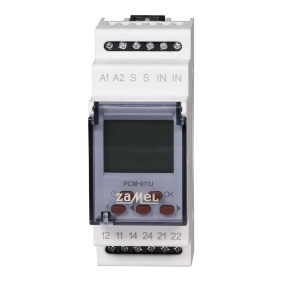
APPEARANCE
must be installed in accor-
dance with standards valid
in a particular country. The
CAUTION
device should be connected
according to the details inc-
Power supply terminals
luded in this operating manual. Installation,
(A1, A2)
connection and control should be carried
out by a qualified electrician staff, who act
in accordance with the service manual and
the device functions. Disassembling of the
device is equal with a loss of guarantee and
can cause electric shock. Before installation
make sure the connection cables are not un-
LCD display
der voltage. The cruciform head screwdriver
3,5 mm should be used to instal the device.
Improper transport, storage, and use of the
device influence its wrong functioning.
It is not advisable to instal the device in the
Control push buttons
following cases: if any device part is missing
or the device is damaged or deformed. In
case of improper functioning of the device
contact the producer.
The symbol means selective
collecting of electrical and electronical
equipment. It is forbidden to put
Relays output (supply) terminals
the used equipment together
(12, 11, 14, 24, 21, 22)
with other waste
INSTRUCTION MANUAL
PCM-07/U
Power supply terminals: A1, A2
Input rated voltage: 24÷250 V AC, 30÷300 V DC
Nominal frequency: 50 / 60 Hz
Rated power consumption: 2 W / 14 VA
Number of operating modes: 25
Operating modes: manual, automatic
Time adjustment range t: 0,1 sec ÷ 99 h 59 min 59,9 sec
Time adjustment accuracy: 0,1 s
LCD display backlight: amber
Time measure accuracy: max. ±3 s / 24 h with 25 °C
Hold up programme time: 10 years
Output relay parameters: 2 NO/NC 16 A 250 V AC1 4000 VA
Number of terminal clamps: 12
Section of connecting cables: 0,2 ÷ 2,50 mm
2
Ambient temperature range: -20 ÷ +60
o
C
Operating position: freely
Mounting: rail TH 35 (PN-EN 60715)
Protection degree: IP20 (PN-EN 60529)
Protection level: II
Overvoltage category: II
Pollution degree: 2
Dimensions: double-modular (35 mm) 90x35x66 mm
Weight: 0,130 kg
Reference standards: PN-EN 60730-1; PN-EN 60730-2-7
PN-EN 61000-4-2,3,4,5,6,11
Operating mode release
terminals (S, S)
Permanent
switch on/switch off
terminals (IN, IN)
Relay mode
Information field
Operating mode
number or time
adjustment number
Automatic mode
Manual mode
VER. 003_15.06.2011
Advertisement

Related Manuals for Zamel EXT10000084


Summary of Contents for Zamel EXT10000084
- Page 1 TOMERS or third parties, to products sold or equipment necessary for the correct operation of products sold; d) defects resulting contact the producer. from force majeure or other aleatory events for which ZAMEL is not liable; e) power supply (batteries) to be equipped with a device in the moment of sale (if they appear);...
- Page 2 OPERATING MODE ADJUSTMENT DESCRIPTION Displayed elements and messages description - operating mode adjustment will be activated in the moment of releasing external input S; press OK to enter; - relay mode - t1 and t2 time adjustment - switch on/switch off Use cursors to choose the right mode;...
Need help?
Do you have a question about the EXT10000084 and is the answer not in the manual?
Questions and answers