Sign In
Upload
Download
Table of Contents
Contents
Add to my manuals
Delete from my manuals
Share
URL of this page:
HTML Link:
Bookmark this page
Add
Manual will be automatically added to "My Manuals"
Print this page
×
Bookmark added
×
Added to my manuals
Manuals
Brands
Dahua Manuals
Monitor
VTH5321GW-W
User manual
Dahua VTH5321GW-W User Manual
Ip indoor monitor
Hide thumbs
1
2
3
Table Of Contents
4
5
6
7
8
9
10
11
12
13
14
15
16
17
18
19
20
21
22
23
24
25
26
27
28
29
30
31
32
33
34
35
36
37
38
39
40
41
42
43
44
45
46
47
48
49
50
51
52
53
54
55
56
57
58
page
of
58
Go
/
58
Contents
Table of Contents
Bookmarks
Table of Contents
Foreword
Important Safeguards and Warnings
Table of Contents
Introduction
Overview
Features
Front Panel
Rear Panel
Cable Connections
Installation
Network Diagram
Configuration
Configuration Process
Vdpconfig
Configuring Door Station
Initialization
Configuring VTO Number
Configuring Network Parameters
Selecting SIP Servers
Adding VTO Devices
Adding Room Number
Configuring Indoor Monitor
Initialization
Network Settings
Project Settings
General Settings
Alarm
Alarm Record
Alarm Settings
Alarm Mode
Unlocking
Arm/Disarm
Arm
Disarm
Elevator Control
Commissioning
Watching Monitoring Videos
Checking Messages
Making Calls
Appendix 1 Cybersecurity Recommendations
Advertisement
Quick Links
1
Table of Contents
2
Cable Connections
3
Installation
4
Network Diagram
5
Configuration
6
Configuring Indoor Monitor
7
General Settings
Download this manual
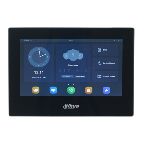
IP Indoor Monitor
User's Manual
V1.0.0
Table of
Contents
Previous
Page
Next
Page
1
2
3
4
5
Advertisement
Table of Contents
Need help?
Do you have a question about the VTH5321GW-W and is the answer not in the manual?
Ask a question
Questions and answers
Related Manuals for Dahua VTH5321GW-W
Monitor Dahua vth15 series User Manual
(29 pages)
Monitor Dahua VTH1500B-S User Manual
Analog indoor monitor, 7" analog vth (18 pages)
Monitor Dahua VTH5221DW-C User Manual
7-inch digital vth (39 pages)
Monitor Dahua VTH Series Quick Start Manual
(22 pages)
Monitor Dahua VTH16 Series User Manual
(22 pages)
Monitor Dahua VTH Quick Start Manual
Digital indoor monitor (20 pages)
Monitor Dahua VTH5421E-H Quick Start Manual
(22 pages)
Monitor Dahua VTH5341G-W User Manual
10-inch android indoor monitor (47 pages)
Monitor Dahua G Series Quick Start Manual
Digital indoor monitor (29 pages)
Monitor Dahua VTH2621GW-WP Quick Start Manual
Digital indoor monitor (29 pages)
Monitor Dahua VTH2621G-P Quick Start Manual
Digital indoor monitor (29 pages)
Monitor Dahua VTH2621GW-P Quick Start Manual
Digital indoor monitor (29 pages)
Monitor Dahua VTH5321GB-W User Manual
Ip indoor monitor (58 pages)
Monitor Dahua E330C Series User Manual
Gaming monitor (34 pages)
Monitor Dahua DHL22-F600 User Manual
(21 pages)
Monitor Dahua F600 Series Manual
(6 pages)
This manual is also suitable for:
Vth5321gb-w
Table of Contents
Save PDF
Print
Rename the bookmark
Delete bookmark?
Delete from my manuals?
Login
Sign In
OR
Sign in with Facebook
Sign in with Google
Upload manual
Upload from disk
Upload from URL


Need help?
Do you have a question about the VTH5321GW-W and is the answer not in the manual?
Questions and answers