Table of Contents
Advertisement
Available languages
Available languages
USE AND CARE GUIDE
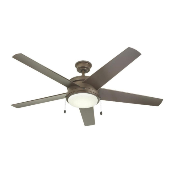
PORTWOOD 60 IN. CEILING FAN
Questions, problems, missing parts? Before returning to the store,
call Home Decorators Collection Customer Service
8 a.m. - 7 p.m., EST, Monday-Friday, 9 a.m. - 6 p.m., EST Saturday
HOMEDEPOT.COM/HOMEDECORATORS
Visual instruction of how to install this fan:
Visit www.homedepot.com and enter either the Item or Model number to find
this fan and click the link of visual instruction in the product overview section.
1-800-986-3460
THANK YOU
THANK YOU
Item #1001 628 059
#1001 628 060
#1001 628 062
Model # YG528-BN
# YG528-EB
# YG528-WH
Advertisement
Chapters
Table of Contents

Related Manuals for Home Decorators Collection PORTWOOD YG528-BN


Summary of Contents for Home Decorators Collection PORTWOOD YG528-BN
- Page 1 USE AND CARE GUIDE PORTWOOD 60 IN. CEILING FAN Questions, problems, missing parts? Before returning to the store, call Home Decorators Collection Customer Service 8 a.m. - 7 p.m., EST, Monday-Friday, 9 a.m. - 6 p.m., EST Saturday 1-800-986-3460 HOMEDEPOT.COM/HOMEDECORATORS Visual instruction of how to install this fan: Visit www.homedepot.com and enter either the Item or Model number to find...
-
Page 2: Table Of Contents
Table of Contents Table of Contents ............Operation ..............Pull Chain Operating Instructions .......... Safety Information ............Light Color Switch Operating Instructions ......Reverse Switch Operating Instructions ........Warranty ................. Care and Cleaning ............Pre-Installation .............. Troubleshooting ............Tools Required ................. Hardware Included .............. -
Page 3: Safety Information
Safety Information To reduce the risk of electric shock, ensure electricity has However, there is no guarantee that interference will not occur been turned off at the circuit breaker or fuse box before in a particular installation. If this equipment does cause harmful beginning. -
Page 4: Warranty
Warranty The manufacturer warrants the fan motor to be free from defects in workmanship and material present at time of shipment from the factory for a period of lifetime after the date of purchase by the original purchaser. The manufacturer warrants the light kit (excluding any glass), to be free from defects in workmanship and material present at time of shipment from the factory for a period of five years after the date of purchase by the original purchaser. -
Page 5: Hardware Included
Pre-Installation (continued) HARDWARE INCLUDED HARDWARE INCLUDED NOTE: Hardware not shown to actual size. Part Part Description Description Quantity Quantity Plastic wire nut Canopy mounting screw with lock washer (preassembled) Blade attachment screw and rubber washer Clevis pin (preassembled) Cotter pin (preassembled) Cross pin (preassembled) Setscrew (preassembled) Collar setscrew (preassembled) -
Page 6: Package Contents
Pre-Installation (continued) PACKAGE CONTENTS PACKAGE CONTENTS Part Part Description Description Quantity Quantity Part Part Description Description Quantity Quantity Mounting bracket (preassembled) Fan motor assembly Canopy ring (preassembled) Blade Canopy Switch housing Canopy bottom cover (preassembled) 28 watt LED Light kit Hanger ball/downrod assembly Glass shade Coupling cover... -
Page 7: Dual Mounting Instructions
Pre-Installation (continued) DUAL MOUNTING INSTRUCTIONS DUAL MOUNTING INSTRUCTIONS This ceiling fan is supplied with two types of hanging assemblies: the standard ceiling installation using the downrod with ball and socket mounting, and the "close-to-ceiling" mounting. The "close-to-ceiling" mounting is recommended in rooms with less than 8 ft. ceilings or in areas where additional space is desired from the floor to the fan blades. -
Page 8: Installation
Installation MOUNTING OPTIONS MOUNTING OPTIONS NOTE: You may need a longer downrod to maintain proper WARNING: To reduce the risk of fire, electric shock, or blade clearance when installing on a steep, sloped ceiling. personal injury, mount the fan to an outlet box marked The maximum angle allowable is 18°... -
Page 9: Assembly
Assembly — Standard Ceiling Mounting Preparing the canopy Preparing the motor □ □ Remove the cotter pin (EE) and clevis pin (DD), and Remove the canopy ring (B) from the canopy (C). loosen the two collar setscrews (HH) from the motor collar. -
Page 10: Close-To-Ceiling Mounting
Assembly — Close-to-Ceiling Mounting Preparing the canopy Preparing the motor □ □ Remove the canopy ring (B) from the canopy (C). Remove the cotter pin (EE), clevis pin (DD) and the two collar setscrews (HH) from the motor collar. □ Remove the mounting bracket (A) from the canopy (C) by loosening the four canopy mounting screws with □... -
Page 11: Hanging The Fan
Assembly — Hanging the Fan Attaching the fan to the electrical box WARNING: To reduce the risk of fire, electric shock or other personal injury, mount the fan only to an outlet box or supporting system marked acceptable for fan support and use the mounting screws provided with the outlet box. - Page 12 Assembly — Hanging the Fan (continued) Making the electrical connections Ground WARNING: To avoid possible electrical shock, be sure conductor Neutral electricity is turned off at the main fuse box before wiring. Black White WARNING: Check to see that all connections are tight, including ground, and that no bare wire is visible at the wire nuts (except for the ground wire).
- Page 13 Assembly — Hanging the Fan (optional) Single Switch Connections Dual Switch Connections □ □ On a single switch the fan and light can be turned on or On a dual switch the fan and light can be turned on or off off together.
- Page 14 Assembly — Hanging the Fan (continued) Standard ceiling mounting Close-to-ceiling mounting WARNING: Locking slots of the canopy (C) are provided WARNING: Make sure the tab on the mounting bracket (A) only as an aid to mounting. Do not leave the fan assembly properly sits in the groove in the hanger ball (E) before unattended until all four canopy mounting screws with lock attaching the canopy (C) to the mounting bracket (A) by...
-
Page 15: Attaching The Fan Blades
Assembly — Attaching the Fan Blades Attaching the fan blades WARNING: To reduce the risk of personal injury, do not bend the blades (H) while installing, balancing the blades (H), or cleaning the fan. WARNING: Do not insert foreign objects between rotating fan blades (H). -
Page 16: Installing The Light Kit
Assembly — Installing the Light Kit Attaching the switch housing Attaching the LED light kit to the mounting ring and glass shade CAUTION: Before starting installation, disconnect the CAUTION: Before starting installation, disconnect the power by turning off the circuit breaker or removing the fuse power by turning off the circuit breaker or removing the fuse at the fuse box. -
Page 17: Operation
Operation PULL CHAIN OPERATING INSTRUCTIONS PULL CHAIN OPERATING INSTRUCTIONS Install two pull chains and fobs (LL) onto the pull chains located in the switch housing (I). Turn on the power and check the operation of the fan. The pull chain controls the fan speed as follows: 1 pull - Extra High, 2 pulls - High, 3 pulls - Medium, 4 pulls - Low, and 5 pulls - Off. -
Page 18: Care And Cleaning
Care and Cleaning Do Do Do not Do not □ □ Check the support connections, brackets, and blade Use water when cleaning. Water could damage the motor, attachments twice a year. Make sure they are secure. or the wood, or possibly cause an electrical shock. Because of the fan’s natural movement, some □... - Page 19 Troubleshooting (continued) Problem Problem Solution Solution □ Verify that all blades and blade bracket screws are secure (most fan wobble problems are caused by loose parts). Once the fan is properly installed, run the ceiling fan for 10 minutes to let the fan self-adjust.
-
Page 20: Service Parts
Service Parts Part Part Description Description Part Part Description Description Mounting bracket (preassembled) Plastic wire nut Canopy ring (preassembled) Canopy mounting screw with lock washer Canopy (preassembled) Canopy bottom cover (preassembled) Blade attachment screw and rubber washer Hanger ball/downrod assembly Clevis pin (preassembled) Coupling cover Cotter pin (preassembled) - Page 21 Questions, problems, missing parts? Before returning to the store, call Home Decorators Collection Customer Service 8 a.m. - 7 p.m., EST, Monday-Friday, 9 a.m. - 6 p.m., EST Saturday 1-800-986-3460 HOMEDEPOT.COM/HOMEDECORATORS Retain this manual for future use.
- Page 22 GRACIAS POR TU COMPRA GRACIAS POR TU COMPRA Apreciamos la confianza que has depositado en Home Decorators Collection al comprar este ventilador de techo. Nos esforzamos para continuamente crear productos de calidad diseñados para mejorar tu hogar. Visítanos por Internet para ver nuestra línea completa de productos disponibles para las necesidades de mejoras de tu hogar.
-
Page 23: Índice
Índice Funcionamiento ............Índice ................Instrucciones de funcionamiento del interruptor de cadena..Información de Seguridad..........Instrucciones para la operación del interruptor de colores de luz ....................Garantía ................Instrucciones de funcionamiento del interruptor de reversa..Pre-Instalación .............. Mantenimiento y Limpieza .......... Especificaciones .............. -
Page 24: Información De Seguridad
Información de Seguridad Para disminuir el riesgo de descarga eléctrica, asegúrate de Sin embargo, no es posible garantizar que el equipo no provoque que la electricidad ha sido apagada en el cortacircuitos o la interferencias en una instalación particular. Si este equipo caja de fusibles antes de comenzar la instalación. -
Page 25: Garantía
Garantía El fabricante garantiza de por vida, a partir de la fecha en que el comprador original lo adquiere, que el motor del ventilador no presenta defectos de fabricación ni de material al momento en que es enviado desde la fábrica. El fabricante garantiza, por un período de cinco años a partir de la fecha de compra por el comprador original, el kit de luces, sin incluir ningun de vidrio, no presentarán ningún defecto de fabricación o de material desde el momento de su salida de la fábrica. -
Page 26: Herrajes Incluidos
Pre-Instalación (continuación) HERRAJES INCLUIDOS HERRAJES INCLUIDOS NOTA: El hardware no se muestra en tamaño real. Pieza Pieza Descripción Descripción Cantidad Cantidad Tuerca de conexión de cables de plástico Tornillo de montaje del cubierta con arandela de cierre (preensamblado) Tornillo para montaje de aspas y arandela de hule Pasador tipo horquilla (preensamblado) Pasador de chaveta (preensamblado) Chaveta atravesda (preensamblado) -
Page 27: Contenido Del Paquete
Pre-Instalación (continuación) CONTENIDO DEL PAQUETE CONTENIDO DEL PAQUETE Pieza Pieza Descripción Descripción Cantidad Cantidad Pieza Pieza Descripción Descripción Cantidad Cantidad Soporte de montaje (preensamblado) Ensamblaje del motor del ventilador Anillo de lacubierta (preensamblado) Aspa Cubierta Caja del interruptor Tapa del fondo de la cubierta (preensamblado) Kit de luces LED de 28W Ensamblado de tubo bajante/bola de soporte Pantalla de vidrio... -
Page 28: Instrucciones De Montaje Doble
Preinstalación (continuación) INSTRUCCIONES DE MONTAJE DOBLE INSTRUCCIONES DE MONTAJE DOBLE Este ventilador de techo viene con dos tipos de ensamblajes de soporte: la instalación de techo estándar con tubo bajante y bola y soporte de montaje; y el montaje “cerca del techo”. El montaje “cerca del techo” se recomienda en habitaciones con techos de menos de 2.44 metros de altura o en áreas donde se desee espacio adicional entre el piso y las aspas del ventilador. -
Page 29: Instalación
Instalación OPCIONES DE MONTAJE OPCIONES DE MONTAJE ADVERTENCIA: Para disminuir el riesgo de incendio, NOTA: Tal vez necesites un tubo bajante más largo para descarga eléctrica o lesiones personales, monta el ventilador mantener la altura mínima adecuada de las aspas al instalar sobre una caja eléctrica marcada como “aprobada como el ventilador en un techo inclinado. -
Page 30: Ensamblado
Ensamblado — Montaje Estándar en Techo Cómo preparar la cubierta Cómo preparar el motor □ □ Retira el anillo (B) de la cubierta (C). Retira el pasador de chaveta (EE) y pasador tipo horquilla (DD), y afloja los dos tornillos de ajuste de □... -
Page 31: Montaje "Cerca Del Techo
Ensamblado — Montaje "Cerca del Techo" Cómo preparar la cubierta Cómo preparar el motor □ □ Retira el anillo (B) de la cubierta (C). Retira el pasador de chaveta (EE), pasador tipo horquilla(DD) y dos tornillos de ajuste de collarín (HH) □... -
Page 32: Cómo Colgar El Ventilador
Ensamblado — Cómo Colgar el Ventilador Cómo fijar el ventilador a la caja eléctrica □ Ajusta firmemente los dos tornillos de montaje. ADVERTENCIA: Para reducir el riesgo de incendio, descarga eléctrica o lesiones físicas, sólo instala el ventilador en una caja eléctrica o sistema de soporte aprobados para ventiladores y usa los tornillos de montaje que vienen con la caja eléctrica. - Page 33 Ensamblado — Cómo colgar el ventilador (continuación) Cómo hacer las conexiones eléctricas Conductor ADVERTENCIA: Para evitar una posible descarga a tierra Caliente Neutro eléctrica, asegúrate de que la electricidad esté apagada de la caja de fusibles principal antes de realizar el cableado. Negro Blanco ADVERTENCIA: Verifica que todas las conexiones estén...
- Page 34 Ensamblado — Cómo colgar el ventilador (opcional) Conexiones de un solo interruptor Conexiones de interruptor doble □ □ Con un solo interruptor, el ventilador y la luz se pueden En un interruptor doble, el ventilador y la luz se pueden encender o apagar juntos.
- Page 35 Ensamblado — Cómo Colgar el Ventilador (continuación) Montaje estándar en techo Montaje "cerca del techo" ADVERTENCIA: Asegúrate de que la pestaña del soporte ADVERTENCIA: Las ranuras de cierre de la cubierta (C) de montaje (A) encaje bien dentro de la ranura de la bola de sólo sirven de ayuda durante el montaje.
-
Page 36: Cómo Montar Las Aspas Del Ventilador
Ensamblado — Cómo Montar las Aspas del Ventilador Cómo Montar las Aspas del Ventilador ADVERTENCIA: Para reducir el riesgo de lesiones personales, no doblar los aspas (H) durante la instalación, compensación de las aspas (H) o limpieza del ventilador. ADVERTENCIA: No insertes objetos extraños entre las aspas (H) en funcionamiento. -
Page 37: Cómo Instalar El Kit De Luces
Ensamblado — Cómo Instalar el Kit de Luces Cómo instalar el caja del interruptor Cómo instalar el kit de luces en la anillo de montaje. LED y la pantalla de vidrio PRECAUCIÓN: Antes de empezar la instalación, corta el PRECAUCIÓN: Antes de empezar la instalación, corta el suministro de electricidad, apagando el cortacircuitos o suministro de electricidad, apagando el cortacircuitos o retirando el fusible en la caja de fusibles. -
Page 38: Funcionamiento
Funcionamiento INSTRUCCIONES DE FUNCIONAMIENTO DEL INSTRUCCIONES DE FUNCIONAMIENTO DEL INTERRUPTOR DE CADENA INTERRUPTOR DE CADENA Instala dos interruptores de cadena y colgantes (LL) en los interruptores de cadena ubicados en la caja del interruptor (I). Enciende la electricidad y verifica el funcionamiento del ventilador. El interruptor de cadena controla las velocidades del ventilador de la siguiente manera: 1 vez: Extra Alto, 2 vez: Alto, 3 veces: Medio, 4: Bajo y 5: Apagado. -
Page 39: Mantenimiento Y Limpieza
Mantenimiento y Limpieza Hacer Hacer No hacer No hacer □ □ Uses agua al limpiarlo. El agua puede dañar el motor o Revisa las conexiones de soporte, soportes y accesorios la madera, o causar descargas eléctricas. de aspas dos veces al año. Verifica que estén seguros. Debido al movimiento natural del ventilador, algunas □... - Page 40 Solución de Problemas (continuación) Problema Problema Solución Solución □ Verifica que todas las aspas y los tornillos de los soportes de aspas estén seguros (la mayoría de los problemas de oscilación del ventilador se deben a piezas sueltas). Una vez que el ventilador ha sido instalado correctamente, enciéndelo durante 10 minutos para que se autoajuste.
-
Page 41: Piezas De Repuesto
Piezas de Repuesto Pieza Pieza Descripción Descripción Pieza Pieza Descripción Descripción Tuerca de conexión de cables de plástico Soporte de montaje (preensamblado) Tornillo de montaje del cubierta con arandela de cierre Anillo de lacubierta (preensamblado) (preensamblado) Cubierta Tornillo para montaje de aspas y arandela de hule Tapa del fondo de la cubierta (preensamblado) Pasador tipo horquilla (preensamblado) Ensamblado de tubo bajante/bola de soporte... - Page 42 ¿Preguntas, problemas o piezas faltantes? Antes de regresar a la tienda, llama al Servicio al Cliente de Home Decorators Collection de lunes a viernes entre De lunes a viernes, entre 8:00 a.m. y 7:00 p.m. (Hora Estándar del Este), y los sábados de 9:00 a.m. a 6:00 p.m. (Hora Estándar del Este).
Need help?
Do you have a question about the PORTWOOD YG528-BN and is the answer not in the manual?
Questions and answers
I need to replace the glass shade on model YG5280D
To replace the glass shade on the Home Decorators Collection model PORTWOOD YG528-BN ceiling fan:
1. Turn Off Power – Disconnect the power at the circuit breaker or fuse box to prevent electric shock.
2. Remove the Light Kit – Unscrew and remove one of the three light kit mounting screws (KK) and loosen the other two. Carefully lower the 28W LED light kit (J).
3. Detach the Glass Shade – Once the light kit is accessible, carefully remove the glass shade (K).
4. Install the New Glass Shade – Position the replacement shade and secure it properly.
5. Reattach the Light Kit – Align the light kit with the mounting ring and secure it using the screws.
6. Restore Power – Turn the power back on and test the fan and light.
This answer is automatically generated
I need to purchase a new glass shade for my YG5280D