Table of Contents
Advertisement
Quick Links
Advertisement
Table of Contents

Subscribe to Our Youtube Channel
Related Manuals for Samsung XA080J


Summary of Contents for Samsung XA080J
- Page 1 Outdoor P8 Product User Manual Model Name: XA080J Model Code: LH080XAJSAC/XX...
-
Page 2: Table Of Contents
Table of contents 1. Safety........................4 1.1 Warning& Symbols..................4 1.2 Safety Guidelines...................5 1.3 Installation instructions..................6 2. Open Package......................7 2.1 Front view......................7 2.2 Side view......................8 2.3 Placing cabinet....................9 3.XAJ8 Product introduction..................10 3.1 Product Specification.................. 10 3.2 Product Appearance..................12 3.3 Product design..................... 14 3.4 Product main components................. - Page 3 10.1 Cleaning....................103 10.2 Calibration....................104 10.3 Replacement steps................. 105 11. Appendix......................117...
-
Page 4: Safety
1. Safety 1.1 Warning& Symbols Grounding The combination of multiple cabinets in an installation results in increased levels of leakage current. In order to avoid risk of electric shock due to high leakage current, proper grounding of the installation is required. Defeating the purpose of the grounding type plug will expose you to the risk of electric shock. -
Page 5: Safety Guidelines
Accredited safety officers must ensure the safety of the site, construction, assembly, connection, use, dismantling, transport etc. Assembly parts are designed for use only with Samsung displays. LEDs use specific materials and manufacturing processing in order to achieve unique advantages.Do not modify and/or replicate any components. -
Page 6: Installation Instructions
1.3 Installation instructions Instructions Read these instructions. Keep these instructions. Heed all warnings. Follow all instructions. Do not block ventilation openings. Please install in accordance with the manufactures instructions. Avoid installation near heat sources such as radiators, heat registers, stoves, or other apparatus (including amplifiers) that produce heat. -
Page 7: Open Package
2. Open Package 2.1 Front view Step 1: Open the top wooden cover Step 2: Open the side wooden cover Step 3: Take the cabinets out from the wooden box. -
Page 8: Side View
2.2 Side view Step 1: Open the top wooden cover Step 2: Open the side wooden cover Step 3: Take the cabinets out from the wooden box. -
Page 9: Placing Cabinet
2.3 Placing cabinet After taking the cabinets out from the wooden box, when you place the cabinet on the ground, please put the back side on the ground first, then carefully put it standing on the ground as shown above to make sure the modules will not be damaged. -
Page 10: Xaj8 Product Introduction
3.XAJ8 Product introduction 3.1 Product Specification Parameter Specification Attribute Outdoor P8 Model Name (VD Common) XA080J Basic Model Name) LH080XAJSAC Pixel Pitch (mm) LED vendor Nationstar LED package type SMD3535 LED package part name RS-3535MWAR LED Lifetime Hr 100,000 ( 24Hr, Luminace 50% down) - Page 11 25 Package Weight(per wooden box) 42kg Package Total Weight (Per wooden 168kg Box) 27 Brightness (cd/m²) Before Calibration >7000 28 Brightness (cd/m²) After Calibration >6300 29 Contrast Ratio(C/R) 3000:1 30 Front Mask for C/R Louver/Mask 31 Viewing angle - Horizontal ( 32 Viewing angle - Vertical ( 33 Bit-depth(bit) 34 Refresh rate(hz) (typical)
-
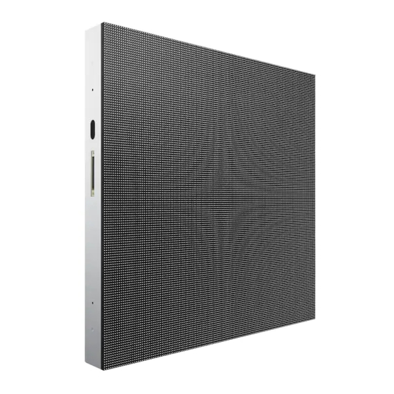
Page 12: Product Appearance
3.2 Product Appearance... -
Page 14: Product Design
3.3 Product design Decomposition chart... - Page 15 Assembly drawing...
-
Page 16: Product Main Components
3.4 Product main components Module Power Supply Receiving Card Monitoring Card... - Page 17 Hub board Power-data cables(16pcs) DC power cables (8PCS)and Flat cables (16 pcs)
-
Page 18: Led Display Screen Components
4. LED display screen components LED display screen connection Sending box(Model Name: LSFNS, Model Code: VG-LSFNS/ZX) Power LED and Switch: Power on or power off the sending box, the LED show the status of sending box. Power supply: AC power input, offer power for sending box. Power LED on back: Show the status of sending card. - Page 19 Function of sending box: 1. HDMI/DVI input; 2. HDMI/external audio input; 3. 12bit/10bit/8bit HD video source; 4. Resolution supported: 2048x1152, 1920x1200, 2560x960; 5. Resolution supported: 1440x900; 6. 1 light sensor interface; 7. Cascading supported; 8. 18bit gray scale processing and presentation; 9.
-
Page 20: Parts List And Parts Bom List
5. Parts List And Parts BOM List 5.1 Accessories list Sending box U Disk 3 core plug DVI cable BN81-15303A BN81-15333A BN81-15312A BN81-15310A R2S8-22-1721 2S8-22-2038 R2J8-22-0125 R2L3-27-0104 USB cable AC power input cable Signal input cable AC power cascade cable BN81-15311A Different code by different project R2L3-27-0105... -
Page 21: Spares List
5.2 Spares list Sending box Receiving card hub board Module BN81-15303A R2S8-22-1721 R4B3-10-0305 R3C6-88-10006 R4X3-08-10000 Power supply LED package Driver IC BN81-15302A BN81-15325A R2D8-22-0159 R2F8-88-0438 R3G1-27-0054 R2K2-22-0219 Mask Screws for Mask AC power input cable Signal cascade cable BN81-15336A Different code by different project L2A8-24-00000 R2W8-22-1410 Different code by different project... -
Page 22: Parts Bom List
5.3 Parts BOM List Samsung Code Code Name Spec Unit Quantity BN81-15303A R2S8-22-1721 Sending box MCTRL600-S(ROHS) R2W8-27-6312 Outdoor cabinet 1280*1280*120mm 4S 40*40 EMC Nova R4X3-08-10000 P8 module system(ROHS) BN81-15312A R2J8-22-0125 3 core plug L 1.5M BN81-15333A 2S8-22-2038 U disk Control software/Setting files... -
Page 23: Service Bom List
5.4 Service BOM List Item Spec Code.No SAMSUNG Spec Photo Quantity Unit LED MOUDLE Module (P8 40*40 4S) R4X3-08-10000 A/S-LED MOUDLE:JDM,R4X3-08-10000,Module (P8 40*40 4S) LED (RS-3535MWAR) R3G1-27-0054 A/S-LED:JDM,R3G1-27-0054,LED (RS-3535MWAR) 1024 A/S-SENDING BOX:JDM,R2S8-22-1721,Sending box SENDING BOX Sending box (MCTRL600-S) R2S8-22-1721 (MCTRL600-S) Power supply A/S-POWER SUPPLY:JDM,R2D8-22-0159,HSP-300-4.2/4.2V... - Page 24 AC Cable ( With conenctor) 3D2-22-10051 A/S-AC CABLE:JDM,3D2-22-10051 ,3*2.5m ㎡ 25CM AC Cable ( With conenctor) 3D2-22-10052 A/S-AC CABLE:JDM,3D2-22-10051 ,3*2.5m ㎡ 40CM Signal cable (with 3D2-23-8261 A/S-LAN CABLE:JDM,3D2-22-8261 ,30CM Cat-5 connector) Signal cable (with R3D3-23-10002 A/S-LAN CABLE:JDM,R3D3-23-10002 ,120CM Cat-5 connector) DC OUTPUT DC output cable (1.0m ㎡...
- Page 25 MASK Mask L2A8-24-00000 A/S-MASK:JDM,L2A8-24-00000,Mask U DISK U DISK 2S8-22-2038 A/S-CD DISK:JDM,R2S8-22-2038,U DISK M10 BOWLS M10 Bowls R2W8-22-0466 A/S-M10 BOWLS:JDM,R2W8-22-0466 ,M10 Bowls SCREW Screws for Mask (M1.2*6) R2W8-22-1410 A/S-SCREW:JDM,R2W8-22-1410,Screws for Mask (M1.2*6)
-
Page 26: Trouble Shooting List
6. Trouble shooting list 6.1 Display screen problem The whole display screen cannot light up Check if the display screen is power on. Check if the connection is broken between Sending box and the display screen, Check if the sending box is normal Check if the first cabinet is working normally in the display screen Check if the brightness setting is 0% Check if the software setting is correct. - Page 27 Part of the display screen cannot light up Check if the part is power on. Check if the power supply is broken Check if the connection is broken between cabinet and cabinet Check if the receiving card is normal. Check if the software setting is correct Check if the program in receiving card is correct Part of the display screen is blinking Check if the connection is broken between cabinet and cabinet...
- Page 28 The display screen is out of control Check if the USB cable is connected well Check if the USB cable is broken Check if the software is running well The display screen display wrong image Check if the connection table setting is correct Check if the software setting is correct Check if the program in receiving card is correct...
-
Page 29: Cabinet Problem
6.2 Cabinet problem The cabinet cannot light up Check if the cabinet is power on Check if the connection is broken between cabinet to cabinet Check if the receiving card is normal Check if the power supply is broken in cabinet Check if the program for receiving card is correct The cabinet is blinking Check if the receiving card is broken... - Page 30 Part of the cabinet cannot light up Check if the power supply is broken Check if the flat cable is broken Check if the DC power cable is broken Check if the HUB board is broken Check if the module is broken Part of the cabinet is blinking Check if the flat cable is broken Check if the HUB board is broken...
-
Page 31: Module Problem
6.3 Module problem The module cannot light up Check if the DC cable is broken Check if the flat cable is broken Check if the module is broken Check if the last module is broken The module is blinking Check if the flat cable is broken Check if the module is broken Check if the last module is broken Block of module is broken or column of module is broken... - Page 32 Row of module is broken Check if the 4973 IC is broken Check if the soldering of the 4973IC is broken Pixel of module is broken Check if the led is broken Check if the soldering of led is broken...
- Page 33 How to check the status of the transmitting card? There are two lights on the transmitting card as shown as below. If everything is right, the Red one will be off and the Green one will be blinking. Otherwise the user needs to check graphics card setting, DVI cable and transmitting card. How to check the status of the receiving card? There are three lights on the receiving card as shown below If everything is right, the Red one is blinking, and the Green one is on (no blinking).
-
Page 34: Installation Guides
7. Installation Guides 7.1 Mechanical requirements and installation Support structure The support structure has to be provided and installed by the customer because they vary from project to project. The following issues must be considered: Weight tolerances: Ensure that the support structure and the floor on which or the wall against which the support structure has to be installed, is qualified to handle the complete weight of the LED display screen.(which can be provided by manufacturer. - Page 35 Installation of cabinets Fixing of connect plate...
- Page 36 Details of installation 1. First measure the under surface of the structure as a horizontal plane and the side of the structure as a vertical plane by spirit level as shown as below 2. First cabinet is placed in the middle of the bottom row with the stud rods in the middle of the corresponding slot as shown as below, do not fix the nuts tightly.
- Page 37 5. Measure the first row by spirit level, make sure it is installed horizontally, then fix the nuts tightly between the cabinets and the connect plates. 6. Place the middle cabinet in the second row, adjust it and fix it but not tight. Make sure it is installed horizontally and vertically, then fix it tightly as shown as below 7.
- Page 38 7.2 Electrical requirements Power system Power voltage must be in the range of the specification value. It is recommended to use a power distribution system (a power distribution system with a separate neutral and grounding conductor in order to avoid large ground current loops due to voltage differences in the neutral conductor.
- Page 39 Lighting Strike Protection of Electric Closet Every electric closet of LED display screen must be installed with lightning protection device equipment. The requirement specification should be same as shown below. Nominal discharge current In (8/20µs) :20 kA The maximum discharge current Imax (8/20µs):40 kA Voltage protection level: Up in ln AC385-505V:≤1.7kV TA ˂25ns...
-
Page 40: Connection Of The Led Screen
8. Connection of the LED screen 8.1 Connection for equipments Connection between Sending box and PC... - Page 41 8.2 Port of Cabinet and serial number paint...
-
Page 42: Connection For Power Cables
8.3 Connection for power cables Usually the length of the AC input cable depend on the distance between the power distribution and LED display screen, it is not certain. The AC cascade cable:3*2.5m ㎡ 150CM/both end plug Attention: For 220-240V AC power voltage countries and areas, each AC input cable can offer power for 3-4 cabinet. -
Page 43: Connection For Data Cables
8.4 Connection for data cables Usually the length of the AC input cable is 50M, but sometimes it depend on the distance between the control room and LED display screen, it is not certain. The signal cascade cable:Cat-5 type 150CM/both end plug... - Page 44 8.5 Cabinet arrangement drawings sample Every project there will be a cabinet arrangement drawing to show how to install the cabinet in turn. This is only a sample to show you what it like. Note: For waterproof, no passing hole on the top cabinet, no passing hole on the bottom cabinet, no passing hole at the far left cabinet, no passing hole at the far right side cabinet For light surge protection, the AC power input cable must be connected to the cabinets with the surge protectors.
-
Page 45: Control System Setting
9. Control system setting 9.1 Software setup It is sample to install the <NovaLCT-Mars> as below: Double-click NovaLCT-Marssetup file,(see Fig.9-1), select <Next> to start, follow the guides to finish the setup. Fig 9-1 When the setup of the < NovaLCT-Mars> is completed, the <LED software> will show up in the <Start/<Program>. -
Page 46: Novalct-Mars Main Interface
9.2 NovaLCT-Mars Main interface This section describes how to use NovaLCT-Mars to set screen parameters as follows: Enter NovaLCT-Mars main interface Step 1:Start “NovaLCT-Mars", click ""User" → "Advanced Login", enter `User login` window as shown in Fig.9-3 Fig 9-3 Step 2:Input the password `admin`, enter the NovaLCT-Mars main interface for advanced users as shown in Fig 9-4 Fig 9-4... -
Page 47: Main Menu
9.3 Main Menu System Reconnect This is used to reconnecting the NovaLCT-Mars to the LED display control Setting system. Screen Config Only accessible by advanced users. This is used for configuration of the LED display control system. Details about this operation will be given in a later part of this manual. Brightness This is used for adjusting the LED display brightness. - Page 48 Tools Calibration Only accessible by advanced users. Select this item to open the calibration page. Details about calibration will be given in a later part of this manual. Screen Control Black out--- Show nothing on the LED display. Lock --- Always show the current image frame of the LED display. Run--- Switch the LED display back to normal from Kill or Lock.
-
Page 49: Tool Bar
9.4 Tool Bar --- the same as Tools->Screen Config in the main menu. --- the same as Tools->Brightness in the main menu. --- the same as Tools->Calibration in the main menu. - -- the same as Tools->Display Control in the main menu. --- the same as Tools->Monitor in the main menu. -
Page 50: Screen Config
9.5 Screen Config To configure a LED display with system configuration files, click Screen Config button fromthe tool bar or select Tools->Screen Config from the main menu of the NovaLCT-Mars application main interface to open the Screen Config window. Shown in Fig.9-5 is the Screen Config window. - Page 51 Sending box setting Enter `Screen Config`, choose `Sending Board` as shown in Fig 9-6. Fig 9-6 In this interface, the user can set up `Sending Board`, `Scan Board` and `Screen Connection Attention: Usually the resolution of transmitting card is bigger than the resolution of the LED display screen.
- Page 52 Scan Board setting Choose the `Scan Board` as shown in Fig 9-7. Fig 9-7 LoadFile: Load programmer file from PC, the file is saved and sent out by the manufacturer. Save file: Save one new programmer file after adjusting parameter. Read From HW: Read the programmer parameter which is saved into the scan boards in cabinets.
- Page 53 Screen connection setting Choose the `Screen Connection` as shown in Fig 9-8. Fig 9-8 Read File: Load connection table file from PC, the file is saved and sent out by the manufacturer. Save File: Save one new connection table file after adjust parameter. Read From HW: Read the connection table parameter which is saved to all the scan boards in cabinets.
-
Page 54: Advanced Color Configuration
9.6 Advanced color configuration Advanced color configuration includes the exit-factory configuration, color space configuration and color temperature table configuration, the target color space plan and color temperature table configured here can be called directed when adjusting brightness. - Page 55 Factory Setting Current Gain:some chips support current gain control; :Default Value: click to restore the default values. RGB Brightness : adjusts brightness of R/G/B colors respectively , or check “synchronization” to adjust the three colors synchronously; : Save the current gain and brightness to hardware; : Import local color configuration file;...
- Page 56 PAL/NTSC: Standard system, click the button with your mouse, the target space will be set to either PAL or NTSC system. Enable color space adjustment:After being checked, the target color space values can be applied to the entire LED display. :...
- Page 57 :Delete selected customized color space information. Select customized color space information to be deleted, click this button, the color space information will be deleted. :Send current calibrated color space and target space to LED display. :Save current calibrated color space and target space to hardware. 2) Color temperature table Click :add color temperature segments, the operation is shown in the picture...
- Page 59 :Compile selected color temperature segment; :Delete selected color temperature segment; :Clear all color temperature segment; :Save the color temperature table to local space. Every project must make a color temperature table (8ea adjust ), and save it into Memory card.
-
Page 60: Adjust The Brightness, Gamma And Current Gain
9.7 Adjust the brightness, Gamma and Current Gain Click Brightness button from the tool bar or select Setting->Brightness from the main menu of the NovaLCT-Mars application main interface to open the Display Adjustment window for brightness, Gamma and color temperature adjustment. There are two methods to adjust the brightness: manual adjustment and automatic adjustment, after adjustment is done, click and save the adjustment... - Page 61 There are two modes for display quality, soft mode and Enhanced mode. Use soft mode for the situation that the environment brightness is not very high. Enhanced mode is better when the background is very bright. Check Custom Gamma, and click to manually define the Gamma table.
- Page 62 Automatic Adjustment The goal of automatic adjustment is to achieve automatic adjustment at present time, There are two methods of adjustment, they are Advanced Adjustment and Adjust by Light Sensor。 Choose the “Automatically Adjustment” option at LED display adjustment interface, click to check current brightness.
- Page 63 Advanced Adjustment You can configure multiple time points, each point can be configured with specified brightness or environment brightness. Specified brightness:The brightness of LED display from certain time on designated by the user, the brightness is fixed. Environment brightness:The brightness of environment from certain time on designated by the user, the software will automatically adjust the LED display brightness in accordance with the parameters set by the users as well as environment brightness information collected by light sensors so that the LED display can exhibit proper brightness under...
- Page 64 1) Add specified brightness Click ,Set the start time, type of adjustment and designated brightness. Click , Choose whether to adjust color temperature, if it’s needed to adjust color temperature, you can choose color temperature segment in the drop down list (color temperature table must be configured in advance, please see description of color temperaturetable in 9.6 advanced color configuration), check “adjust Gamma”, drag scroll bar to adjust Gamma value.
- Page 65 After parameter configuration is done, click ,to add another designated brightness. 2) Add environment brightness Click ,to set start time and type of adjustment Click ,choose whether to adjust color temperature, if it’s needed to adjust color temperature, you can choose color temperature segment in the drop down list (color temperature table must be configured in advance, please see description of color temperature table in Advanced color configuration), check “adjust Gamma”...
- Page 66 3) Configure light sensors Environment brightness is detected by light sensors, a system must be equipped with light sensors, and you must configure the light sensor before adding environment brightness. :Detect light sensors connected to sending boards and function card, the light sensors that connected to function card must be set as the external device.
- Page 68 4) Save the configuration After the wizard settings is fished, go back to the main interface of automatically adjustment, you can click to add some settings of environment brightness or specified brightness , it's also be allowed to edit or delete the added brightness settings. After all the operations is finished , it's must to click...
- Page 69 Adjust by Light Sensor One time point will be generated by LCT automatically, and it will be configured with environment brightness by default. 1) Click ,check “Adjust by Light Sensor”,then click 2) If you have not finished configuration of light sensor, it's need to configure the light sensor then, the detailed operation, please refer to the step 3) in 5.3.2.1 advanced adjustment.
- Page 70 4) All operations are finished,click . Auto Brightness Time Interval The following steps are to set the time interval for auto brightness. Step 1 Click right button on the circled panel icon (as shown in Fig.9-9) and select Brightness Advance Setting from the pop-up menu (as shown in Fig.9-10) to open the Advance Setting window (as shown in Fig.9-11).
- Page 71 Step 2 Set the values for Detect Period and Read times of light sensors. Detect Period is the time period the light sensors measure the environment brightness. Read times of light sensors is the times that NovaLCT-Mars reads the measurement results of the light sensors. Thus the auto brightness time interval is the production of Detect Period and Read times of light sensors.
-
Page 72: Display Control
9.8 Display Control Click Display Control button from the tool bar or select Tools->Display Control from the main menu of the NovaLCT-Mars application main interface to open the Screen Control window. Kill Show nothing on the LED display. Lock Always show the current image frame of the LED display. Switch the LED display back to normal from Kill or Lock. -
Page 73: Check Hardware Info
9.9 Check Hardware Info Click Tool ->Hardware Information from the main menu to open the Hardware Information page. Shown in Fig.9-12 is the Hardware Information page. Fig 9-12 Current Serial Port If more than one Mars serial LED display control system is connected to the computer, set the serial port through which the Mars serial LED display control system to be configured as the current serial port. -
Page 74: Brightness/Color Calibration
9.10 Brightness/Color Calibration Online Calibration In online calibration, NovaCLB connects with NovaLCT-Mars through network. Data and instructions for LED display calibration are exchanged through the network. Shown in Fig.9-13 is the page for online calibration. Fig 9-13 Current Serial Port This is the serial port through which the LED display to be calibrated is connected to the computer. - Page 75 Save button in the Enable/Disable Calibration panel Click this button to save the calibration switch status (enable or disable) to the hardware. Save button in the communication log panel Click this button to save the communication log to a text file. Manage Coefficients This page is to adjust the calibration coefficients for better calibration performance.
- Page 76 Upload Coefficients This is to upload the calibration coefficients and Adjust lines coefficients to the LED display the LED display control system can use the coefficients to improve the image quality of thus the display. Step 1 Browse Click this button to select the calibration coefficients database file to be uploaded. Type The type of the selected calibration coefficients database is shown here.
- Page 77 Topology or List Selected this option to upload calibration coefficients to the cabinets selected in the cabinet array sketch map or the cabinet list. (If the current LED display is a simple or a standard display, the sketch map of the cabinet array will be shown after this option is selected. Otherwise, if the current is a complex display, the show is the cabinet list.) Zoom The zoom slide bar is for zoom in or out the cabinet array sketch map.
- Page 78 Click Next to open the page for Step 3.
- Page 79 Step 3 Shown in Fig.9-15 is the page for Step 3. Fig 9-15 Fast Upload The uploading speed will be set as maximum thus the time required for uploading is minimized if this option is selected. Stable Upload The uploading process is more stable and reliable for this option. But the time required is longer than the Fast Upload option.
- Page 80 Fig 9-16 Open Click this button to open an existing database to save the read back calibration coefficients. The new saved coefficients will replace the old ones according to the position. If the coefficients array size of the opened database is smaller than that of the current display, the save operation will be failed.
- Page 81 Fig 9-17 Screen-Database Select this option if it is to save the calibration coefficients to a new screen database. Cabinet-Database Select this option if it is to save the calibration coefficients to a new cabinet database. Create Click this button to create a new screen database or a cabinet database according to the settings.
- Page 82 Fig 9-18 Screen Check this option if the calibration coefficients for the whole display are to be saved. If the database for saving the coefficients is a cabinet database, this option will be unavailable. Pixel Check this option to select the pixel area for which the calibration are to be saved. If the database for saving the coefficients is a cabinet database, this option will be unavailable.
- Page 83 Set coefficients for a new scan board Step 1 Specify the LED display area that the new receiver card (scan board) works for. Shown in Fig.9-19 is the page for specifying the area. Fig 9-19 Step 2 Select the calibration coefficient source. The coefficients could be from a database (the Database option) or generated according to those of the surrounding receiver cards (the Refer to Surrounding Scan Board option).
- Page 84 Fig 9-20 Browse Click this button to select the database that the calibration coefficients for the new receiver card are from. If the selected is a cabinet database, the cabinet ID should also be specified from the Cabinet ID drop list. Cabinet ID If the selected database is a cabinet database, the IDs of the cabinets of which the calibration coefficients are contained in the database will be list in the drop list.
- Page 85 Fig 9-21 Step 3 If the calibration coefficients from Step 2 are not satisfying, they can be adjusted. There are two type of adjustment, Simple and Advanced. Shown in Fig.9-22 and Fig.9-23 are the pages for Simple and Advanced adjustment respectively. Fig 9-22...
- Page 86 Use the slide bar to adjust the red brightness of the calibration coefficients. Green Use the slide bar to adjust the green brightness of the calibration coefficients. Blue Use the slide bar to adjust the blue brightness of the calibration coefficients. Advanced Click this item to switch to the advanced adjustment page.
- Page 87 Fig 9-24 Set coefficients for a new module Step 1 Specify the cabinet which the new module is in. this can be done through the page shown in Fig.9-25 Fig 9-25...
- Page 88 Step 2 Double click the selected cabinet to open the page for specifying the new module. Shown in Fig.9-26 is the page for specifying the new module. Fig 9-26 Module Size Set the pixel array size of a module here. NovaLCT-Mars divides a cabinet into modules according to the module pixel array size and the cabinet pixel array size.
- Page 89 Fig 9-27 Step 4 Adjust the calibration coefficients if the generated coefficients are not satisfying. The adjustment page is similar to that for a new receiver card. Step 5 Save the calibration coefficients to the hardware (FLASH) so they won’t be lost when the LED display is powered off.
- Page 90 Step 2 Select the adjustment type. If Adjust Own Effect option is selected, the color adjustment of selected area is independent to the other areas of the LED display. If Effect As Other Selected Area option is selected, the color of the selected area will be adjusted according to the reference area color.
- Page 91 Step 3 Adjust the calibration coefficients. This step is similar to that for a new receiver card. Step 4 Click the Save button to save the adjusted calibration coefficients to the hardware. The save coefficients won’t be lost even the system is powered off. Shown in Fig.9-31 is the page for saving the calibration coefficients.
- Page 92 Apply Apply adjustment operations to the selected area. Erase or reload Coefficients Shown in Fig.9-33 is the page for erasing/reload calibration coefficients. Erase coefficients: erasing calibration coefficients of the whole display or any cabinets. Reload coefficients: reload the calibration coefficients lastly saved in hardware. Fig 9-33 Screen Select this option to erase all calibration coefficients for the whole display.
- Page 93 Reset coefficients Reset correction coefficients of the full screen or the specified area in accordance with the size of module or pixel. Complete all operation of reset coefficient, click on the "Save To HW", The correction coefficient reset will be effective...
-
Page 94: Monitor The System
9.11 Monitor the System Mars series control system provides monitoring function, covering DVI signal of sending card, hardware status, temperature, humidity, smoke, fan, power supply, cabinet, and door status. Supports ordinary screen and screen combination surveillance. Click to enter the monitoring interface, and click to check hardware status data of all screens of this system. - Page 95 Refresh period Modify refresh period and reread times when reading the status failed at the refresh period interface, wherein the period is the period of refreshing the monitoring data. If all screens are registered to the NovaCare server, check “Auto refresh” to perform remote monitoring.
- Page 96 Hardware configuration :Click to enter the advanced setting of monitor, as shown in the figure below. Each receiving card is connected with one monitoring card by default. Click to pop up with the interface below. Please set the number of receiving cards (0 or 1) according to the actual situation...
- Page 97 Click to restore the default values immediately. Connect Monitor Board Monitor Boards are required for certain status and parameters monitoring. Select this option to get those status and parameters under monitoring. Refresh Humidity If this option is selected, the humidity within the cabinets will be under monitoring. Refresh Smoke If this option is selected, the smoke within the cabinets will be under monitoring.
- Page 98 The difference lies in that the number of fan (power supply) of every cabinet can be set to be different when separately performing refreshing setting to every screen, as shown in the following figure:...
- Page 99 Attention: Because the fan is controlled by the temperature control IC, it is not error when the fan stops in the temperature range 20°C-30°C. It means the temperature control IC is working well. Other temperature if the fan stops, it means there is problem of the fan. Data alarm configuration Display alarm or fault information when setting the temperature, humidity, fan speed and voltage critical value.
- Page 100 Control configuration Select one screen or all screen to perform monitoring configuration separately. Click to add control information; the figure below shows adding temperature control information, and the figure shows adding smoke control information.
- Page 101 Email setting Shown below is the page for email notification setting. Set the email notification according to the instructions given on the page. If the sending system report Email is enabled, the regular sending could be set.
- Page 102 Email Log Shown below is the History window for checking the notification emails. Information about the notification emails, such as date, error display index, email recipients and so on can be checked through this window. The details of operation for NovaLCT-Mars, please refer to the <Nova M3 LED Display Control System UserManual-V4.4.1.pdf>...
-
Page 103: Servicing
10. Servicing 10.1 Cleaning For outdoor LED display screen Due to outdoor use the LED display screen are exposed to all kinds of weather conditions. Sand, dust, smog and other dirty things on the LED display and because of that the performance of the LED display may be effected, So regular cleaning on LED display is recommended. -
Page 104: Calibration
10.2 Calibration Factory calibration In order to achieve color uniformity among all cabinets of the same display the cabinets can be color calibrated to improve display effect of the LED display screen. The manufacturer can do calibration before goods are delivered out of factory. Site calibration When the LED display screen is running for a long time, for example for one year, some part of the display screen may play a different image from other parts. -
Page 105: Replacement Steps
10.3 Replacement steps Front Service: Module Power off the cabinet where the module is in Remove the module from front by front service tool as shown below Remove the screws which connect the power-data cable into the bad module by short screwdriver and then take off the bad module from cabinet by hand as shown below Bring a new module and connect the power-data cable into the new module by short screwdriver as shown below... - Page 106 Calibration data updating Open the control software MCTRL-mars, then Click “Settings”→Click “Module Flash” going to the interface as shown below: Choose “Auto Upload Module” Flash Check :Checking if the module flash is working View Calibration coefficients in receiving card: View the calibration coefficients in the receiving card which the new module is in.
- Page 107 Open Power box Before replace the bad parts in/on power box, you need to remove all the modules which in on the front of the power box. Put down the power box as shown below Open the door of the power box as shown below...
- Page 108 Power-data cable Power off the cabinet where the power-data cable is in Remove the modules which connect the bad power-data cable by front service tools as same as the module replacement steps. Remove the screws which connect the bad power-data cable into the modules by short screwdriver and take away modules as shown below Remove the screws which connect the bad power-data cable into the power box by screwdriver and take away the bad power-data cable as shown below...
- Page 109 Power supply Power off the cabinet where the power supply is in Remove the fixing board by hand as shown below Take off all the cables connected to the power supply by screwdriver as shown below Take away the bad power supply as shown below Bring a new power supply and put it in the power box then connect the cables to power supply by screwdriver as shown below Fix the new power supply in the power box with fixing board as shown below...
- Page 110 Receiving card Power off the cabinet where the receiving card is in Remove the cat-5 cable from the receiving card as shown below Remove the bad receiving card from box by screwdriver as shown below Bring a new receiving card and put it in the power box then install it by screwdriver as shown below Install the cat-5 cable into receiving card as shown below Power on the cabinet.
- Page 111 Monitoring card Power off the cabinet where the monitoring card is in Remove all the monitoring cables from the bad monitoring card by screwdriver as shown below Remove the bad monitoring card by screwdriver then take off it as shown below Bring a new monitoring card and put it in the power box then install it by screwdriver as shown below Install all the monitoring cables into the new monitoring card as shown below...
- Page 112 Hub board Power off the cabinet where the hub board is in Remove all the cables and all the card on the HUB board as shown below Remove the Hub board from the power box by screwdriver then take away it as shown below Bring a new hub board then install it into power box by screwdriver as shown below Install all the cards and all the cable on the hub board as shown below...
- Page 113 Transfer board Power off the cabinet where the transfer board is in Remove the cables on the bad transfer board as shown below Remove the transfer board from the power box by screwdriver as shown below Bring a new one and install it on power box then install the cables on it as shown below Power on the cabinet...
- Page 114 Power off the cabinet where the fan is in Remove the fan cable from HUB board then remove the fan from power by screwdriver as shown below Bring a new fan and install it into the power box then install the fan cable into HUB board as shown below Power on the cabinet...
- Page 115 DC Cable Power off the cabinet where the cable is in Remove the cables from the transfer board and the power supply as shown below Bring a new one and install it as shown below Power on the cabinet Flat Cable Power off the cabinet where the cable is in Remove the cables from the transfer board and the hub board as shown below Bring a new one and install it as shown below...
- Page 116 Rear Service: Module Power off the cabinet where the module is in Remove the power-data cable by screwdriver then remove the bad module as shown below Bring a new one and install it on cabinet as shown below Power on the cabinet Other parts the replacement steps are same as doing it for front service...
-
Page 117: Appendix
Product damage caused by customer`s mishandling or wrong repair. If a product damage is caused by: External impact or drop. Use of supplier or separately sold product unspecified by Samsung. Repair from a person besides an engineer of outsourcing service company or partner of Samsung Electronics Co.Ltd.
Need help?
Do you have a question about the XA080J and is the answer not in the manual?
Questions and answers